Call us 24/7+86 18150137010
Welcome to the official website of Hong Kong Industrial Control Trading Co., Ltd.
Call us 24/7+86 18150137010

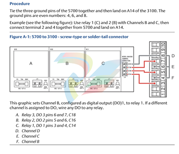
GSI127 galvanic separation unit MEGGITT VIBRO-METER GSI 127 244-127-000-017 A1-B02 MODULE

KEY FEATURES AND BENEFITS 

• From the vibro-meter ® product line

• Power supply for sensors and signal conditioners with a current output or a voltage output 

• 4 kVRMS galvanic separation between the sensor side and the monitor side 

• 50 VRMS galvanic separation between the power supply and the output signal (floating output) 

• High rejection of frame voltage 

• µA to mV transfer function for current-signal transmission over longer distances 

• V to V transfer function for voltage-signal transmission over shorter distances 

• Ex certified for use in potentially explosive atmospheres (hazardous areas) 

• Compatible with industry standard IEPE (integrated electronics piezo electric) vibration sensors KEY BENEFITS AND FEATURES (continued) 

• Removable screw-terminal connectors 

• DIN-rail mounting 

• No ground connection needed APPLICATIONS 

• All vibro-meter ® measurement chains with current or voltage outputs 

• Safety-related applications DESCRIPTION The GSI127 is a galvanic separation unit from Meggitt’s vibro-meter ® product line. It is designed for operation with the signal conditioners, charge amplifiers and electronics (attached or integrated) used by various vibro-meter ® measurement chains and/or sensors.

DESCRIPTION (continued)

Compatible devices include the IPC707 signal conditioners (charge amplifiers) used by CAxxx piezoelectric accelerometers and CPxxx dynamic pressure sensors (and older IPC704 signal conditioners too), the IQS9xx signal conditioners used by TQ9xx proximity sensors (and older IQS4xx signal conditioners too), the attached or integrated electronics used by CExxx piezoelectric accelerometers, and the integrated electronics used by the VE210 velocity sensor. The GSI127 is also compatible with industry standard IEPE (integrated electronics piezo electric) vibration sensors, that is, the integrated electronics used by constant-current voltage output sensors such as the CE620 and PV660 (and older CE680, CE110I and PV102 sensors too). The GSI127 galvanic separation unit is a versatile unit that can is used for the transmission of high frequency AC signals over long distances in measurement chains using current-signal transmission or as a safety barrier unit in measurement chains using voltage-signal transmission. More generally, it may be used to supply any electronic system (sensor side) having a consumption of up to 22 mA.

The GSI127 also rejects a large amount of the frame voltage that can introduce noise into a measurement chain. (Frame voltage is the ground noise and AC noise pickup that can occur between the sensor case (sensor ground) and the monitoring system (electronic ground) ). In addition, its redesigned internal power supply results in a floating output signal, eliminating the need for an additional external power supply such as an APF19x. The GSI127 is certified to be installed in an Ex Zone 2 (nA) when supplying measurement chains installed in Ex environments up to Zone 0 ( [ ia ] ). The unit also eliminates the need for additional external Zener barriers in intrinsic safety (Ex i) applications. The GSI127 housing features removable screw terminal connectors that can unplugged from the main body of the housing to simplify installation and mounting. It also features a DIN-rail mounting adaptor that allows it to be mounted directly on a DIN rail. For specific applications, contact your local Meggitt representative.

SPECIFICATIONS

Environmental General Temperature •Operating :−40 to 70 °C (−40 to 158 °F) •Storage :−40 to 85 °C (−40 to 185 °F) Humidity (according to IEC 60068-2-30) •Operating : 90 % max. non-condensing •Storage : 95 % max. non-condensing Vibration (according to IEC 60068-2-6) : 1 g peak above resonant frequency and 0.15 mm peak below (5 to 35 Hz, 90 minutes /axis) Shock acceleration (according to IEC 60068-2-27) : 6 g peak (half sine-wave, 11 ms duration, 3 shocks/axis) Induced signal susceptibility (according to IEC 61000-4-4/5) :Performance criteria B RF susceptibility (according to IEC 61000-4-3) :Performance criteria A RF emissions – limits at 1 m (according to IEC 61000-4-3) :< 60 dBµV/ m (quasi-peak) from 30 to 230 MHz. < 67 dBµV/ m (quasi-peak) from 230 to 1000 MHz. Electrostatic discharge (according to IEC 61000-4-2) :Performance criteria B

https://static.websiteonline.cn/website/script/pdfjs/web/viewer.html?file=https%3A%2F%2Fpro7af9ac-pic10.websiteonline.cn%2Fupload%2FDS_GS3960.pdf&nodownload=1

Honeywell C300 controller CC-PCNT02 PN:51454551-275

Honeywell C300 controller module CC-PCNT02 PN:51454551-275 is a high-performance and high-reliability industrial automation controller module, belonging to Honeywell C300 series. The module adopts 32-bit RISC microprocessor, which has powerful processing ability, supports various control strategies (such as PID control, fuzzy control, etc.) and communication protocols (such as RS-232, RS-485, CAN, etc.), and is suitable for various application scenarios such as industrial process control, data acquisition and signal processing.

The main technical parameters of CC-PCNT02 module include:

Input voltage range: 24V DC, output voltage range: 0~10V DC.
Operating temperature range:-40 C to+85 C.
Memory configuration: 128KB SRAM and 2MB Flash memory.
Input/output points: 64 digital input/output points and 16 analog input/output points.
Protection grade: IP65.
The module is widely used in chemical industry, petroleum, natural gas, pharmacy, water treatment, metallurgy and other industrial fields, which can meet complex control requirements and provide flexible configuration options.

Honeywell
FC-PSU-UNI2450
FC-BKM-0001
FC-DCOM-232/485
PCNT02
PAIHA1
PAOHA1
FC-SDO-0824
FC-TSDO-0824
PDILA1
FC-TSDI-1624
PDODA1
FC-SDI-1624

DS200ADGIG1AAA Auxiliary Genius Interface Board

Part Number : DS200ADGIG1AAA

SKU : DS200ADGIG1AAAGBTC

Manufacturer : GE Boards & Turbine Control

Series: Mark V DS200

Ge’s ds 200 ad gig 1 aa board assembly is a part of the company’s Mark V turbine control system series Speedtronic system, as mentioned above. This ds 200 ad gig 1 aa printed circuit board (PCB for short) is actually not the Mark V series auxiliary Genius interface board specially manufactured for Mark V series. This will be three important A-level product revisions of DS200ADGIG1 mother printed circuit board without this general electric product. Mark V series to which this special ds 200 ad gig 1 aa board belongs is generally out of date, because general electric company stopped its production in one of many years after its original mark series was launched. The greater Mark V series of ds 200 ad gig 1 aa equipment is generally out of date, but it has a continuous demand in the larger automation industry market, because it is one of the latest products in the GE Mark product series, and integrates the patented technology of Speedtronic control system into its various product series. The technology of Speedtronic control system in ds 200 ad gig 1 aa board and its larger Mark V series was first released in the middle and late 1960s together with the main concepts of Mark I series.

Hardware tips and specifications

This ds 200 ad gig 1 aa auxiliary Genius interface board consists of a set of specific hardware component contents and component specifications. Fortunately, we can find these contents in the Mark V series raw data manual on the Internet. Every corner of ds 200 ad gig 1 aa motherboard is factory drilled. Ds 200 ad gig 1 aa device is designed with a carrier board and an accessory daughter board, marked with GE logo and wiring code. Although the edge of the circuit board is made of traditional PCB layer, most of the circuit board is covered with black topcoat, which is a typical feature of Mark V series products. There are almost no mounting components in this part of the circuit board. At the top third of ds 200 ad gig 1 aa printed circuit board, the coating disappears, and there are several right-angle and vertical pin connectors, integrated circuits, resistors and test points on the circuit board. The board also has many jumper pins, allowing users to change the circuit to meet their specific needs. The board has four brackets connecting the daughter board and the main board.

Mark V daughter board for DS200ADGIG1AAA PCB has built-in additional integrated circuits. If you need more information about each chip, these ICs are usually marked with the original manufacturing number on the top surface. The board is about 8 inches by 6 inches, which is convenient because it is usually installed in the drive cabinet of Mark V series. The device will be screwed using factory-made holes along the edge of the plate. This ds 200 ad gig 1 aa auxiliary Genius interface board is regarded as an electrostatic sensitive GE PCB, so the attached grounding strap must be used when unpacking this Mark V series product. Ge has made three major modifications to ds 200 ad gig 1 aa, which may increase the overall size and performance specifications of the device.

General electric company provides some general considerations about standardizing the use of ds 200 ad gig 1 aa auxiliary Genius interface board. As mentioned in GE’s original instruction manual, DS200ADGIG1AAA PCB is not designed to download EEPROM data of Mark V-series driver, because it must be downloaded using Mark V-series RS-232 port or keyboard.

DS200ADGIG1AAA Auxiliary Genius Interface Board

ECT-16-0045 UniOP ECT-16, ELT-16 and ERT-16

Technical 

Data Display Graphical resolution   

Graphical capabilities   Touch panel   Power supply     Program Memory   Communication ports   Aux Port Alarms Alarm info page  ECT-16 STN Color 5.6”    ELT-16 Monochrome Electroluminescent 5.6”    ERT-16 Monochrome  LCD 5.6” 320×240 YES Resistive touch screen 24 VDC 512 KB Flash EPROM (64 KB reserved for protocol)    Expandable to 1 MB 1 RS-232 port (PC/Printer) 1 RS-232, RS-485, CL 20 mA PLC (-0045)  YES   1024 YES Number of variables per page Unlimited 

Page size  16 rows Macro Editor Hardware Clock/Calendar Historical event list   

Recipes UniNET Network   

Password Printer  YES YES 1024   32 KB SERVER / CLIENT  YES   YES

Related models

ECT-16-0045: It has been mentioned many times as a color touch screen operating interface, which is used in the field of industrial control, and is specifically described as “operator interface color touch screen”.

ETOP11-0050: It appears many times as a touch screen with color operation interface, which is similar to ECT-16-0045 and also belongs to the UNIOP touch screen series.

ETP03: A portable man-machine interface device, equipped with a 3.8-inch color touch screen, supports interfaces such as RS-232 and RS-422/485, and is suitable for industrial automation scenes.

ETP06: A small touch screen device with various interface options, suitable for industrial control applications.

ETP06-0050: A touch screen model, which is related to ETP06 series. The specific function and use are not specified in detail.

ETP10C: A touch screen model, suitable for industrial control field.

ETP307: A 7-inch color touch screen device for industrial control operation interface.

ETP307: Another device described as a 7-inch color touch screen supports a variety of industrial communication protocols.

BKDC-16T, BKDL-16T and BKDR-16T: These models belong to UNIOP’s touch screen series and provide different functions and specifications.

ELT-16: A touch screen model suitable for industrial control scenes.

MDK-VGA-045: A touch screen panel, similar to UniOP ECT-16-0045.

ECT-16-0045 UniOP ECT-16, ELT-16 and ERT-16

DS200AAHAH1AED Arcnet Hub LAN Driver Board

About the DS200AAHAH1AED

The DS200AAHAH1AED is a GE created ARCNET LAN Driver Board. This board was produced to be a component of the GE Mark V LM series of Speedtronic hardware. This board is no longer being supported by GE and may be a little hard to locate. Please consult AX Control for the availability of the DS200AAHAH1AED because we do attempt to keep it in stock. While this DS200AAHAH1AED PCB’s greater Mark V Series may exist as a legacy product series, it also is one of the final General Electric Speedtronic product series to make use of the patented Speedtronic control system technology first introduced with the rollout of the Mark I Series in the late 1960s. This DS200AAHAH1AED printed circuit board or PCB for short is not the original ARCNET LAN Driver Board created for insertion in the Mark V Series automated drive assembly; that would be the DS200AAHAH1 parent ARCNET LAN Driver Board not making use of this DS200AAHAH1AED device’s three significant product revisions.

Hardware Tips and Specifications

The DS200AAHAH1AED is a PCB that was meant to function within the MARK V’s control panel. It is also identified as an ARCNET Connection Board (AAHA). Like its name would suggest, this board is designed to act as a connection that links the main Control Engine and external drives to the ARCNET. The control engine actually resides within the <R> core. Two AAHA boards are actually needed within the <R> core. One of the boards needed by the core is a board that connects the COREBUS to the <R> core. In doing so, the control engine is allowed to communicate to the I/O cores that are also held within the <R> core.  This board also can connect to the PANA board. The second board grants a Stage Link connection to the user interface and the <R> core. The DS200AAHAH1AED is a very small and simple board. It has three communications ports on the top side. The leftmost port isn’t actually used and is an EBNC port. Beside of it are the ARCBNC-A and ARCBNC-B ports. 

​323A2374P3 small terminal control display Mark V DS20 series 

Ge Speedtronic Mark V gas turbine control system is a version of ge’s long series of high-reliability electro-hydraulic control (EHC) systems for steam and gas turbine control.

About the 323A2374P3

The 323A2374P3 GE Display is designed as a mini terminal for use with General Electric’s Mark V turbine control system. The Mark V turbine control system has been used for managing industrial gas, steam, and wind turbines for decades, powered by General Electric’s patented Speedtronic control system technology. The Mark V Turbine Control System Series is only one of several Speedtronic systems our company maintains on-hand stock for. If you need replacement parts for any of the Speedtronic systems, from the Mark I to the Mark VIe, please talk to our team or look through our online inventory for more information. This 323A2374P3 Mini-Terminal Control Display is not functionally-named as many other component products within the Mark V Series are, which means that the contents of this personalized product page with be primarily based upon a visual inspection of the model, as conducted by one of our knowledgeable and experience printed circuit board technicians.

Hardware Tips and Specifications

The 323A2374P3 is a small LCD keypad and screen combination. This 323A2374P3 product functions as a mini terminal/point of control for the Mark V Series automated drive assembly that it was originally designed and manufactured for. The 323A2374P3 unit can mount directly to a unit using screw mounts and connects with the associated plug and wiring available along one long edge of the display. While this 323A2374P3 product is a member of the Mark V Turbine Control System Series from General Electric, it is not afforded a standard version of General Electric functional product number; most likely a result of its odd existence as a keypad and LCD screen display product. With this being true, if this 323A2374P3 device makes use of any particular Mark V Series assembly version, functional product acronym, base printed circuit board coating style, or functional product revision, it is unfortunately not able to be confirmed on this 323A2374P3 personalized product page here.

The 323A2374P3 display has a single small LCD panel that offers a two-line 40 character display. Below this display, the 323A2374P3 device’s front panel has four lines of touch-sensitive membrane switches. These keys offer more than one function, as they utilize the shift key located in the bottom left corner of the unit to access the secondary functions. The panel includes F1 through F20 keys, as well as scroll up and down, numeric keys, more, less, and raise/lower keys. Also included in this 323A2374P3 product offering’s keypad panel are a set of three buttons seemingly pertinent to the greater Mark V Series automated drive’s diagnostic fault alarm, labeled as “ALARM SIL,” “ALARM ACK,” and “ALARM RESET.” Refer to General Electric manuals for a more detailed look at this unit as well as specifics regarding its handling and installation; this 323A2374P3 product is identifiable as a GE Drive Systems Mini-Terminal product through the insertion of several General Electric logos and the GE Drive Systems company name on the front of the 323A2374P3 keypad itself.  Manuals and user guides should have been provided with your original purchase from the OEM.

323A2374P3-GE

Micro Motion™ 5700 Transmitters with Intrinsically Safe Outputs

Before you begin 

 About this document This manual provides information on planning, mounting, wiring, and initial setup of the Micro Motion 5700 transmitter. For information on full configuration, maintenance, troubleshooting, or service of the transmitter, see the . The information in this document assumes that users understand basic transmitter and sensor installation, configuration, and maintenance concepts and procedures. Hazard messages This document uses the following criteria for hazard messages based on ANSI standards Z535.6-2011 (R2017). 

 DANGER Serious injury or death will occur if a hazardous situation is not avoided. WARNING Serious injury or death could occur if a hazardous situation is not avoided. CAUTION Minor or moderate injury will or could occur if a hazardous situation is not avoided. NOTICE Data loss, property damage, hardware damage, or software damage can occur if a situation is not avoided. There is no credible risk of physical injury. Physical access WARNING Unauthorized personnel can potentially cause significant damage and/or misconfiguration of end users’ equipment. Protect against all intentional or unintentional unauthorized use. Physical security is an important part of any security program and fundamental to protecting your system. Restrict physical access to protect users’ assets. This is true for all systems used within the facility.

Installation checklist 

 □ If possible, install the transmitter in a location that will prevent direct exposure to sunlight. The environmental limits for the transmitter may be further restricted by hazardous area approvals. 

 □ If you plan to mount the transmitter in a hazardous area: 

WARNING 

 — Verify that the transmitter has the appropriate hazardous area approval. Each transmitter has a hazardous area approval tag attached to the transmitter housing. 

 — Ensure that any cable used between the transmitter and the sensor meets the hazardous area requirements. 

 — For ATEX/IECEx installations, strictly adhere to the safety instructions documented in the ATEX/IECEx approvals documentation available on the product documentation DVD shipped with the product or at . 

 □ Verify that you have the appropriate cable and required cable installation parts for your installation. For wiring between the transmitter and sensor, verify the maximum cable length does not exceed 1,000 ft (305 m). 

 □ Ensure that you use a twisted-pair instrument cable for all output connections. 

 □ You can mount the transmitter in any orientation as long as the conduit openings do not point upward. Installing the transmitter with the conduit openings facing upward risks condensation moisture entering the transmitter housing, which could damage the transmitter. Following are examples of possible orientations for the transmitter. Preferred orientation Alternate orientations 

 □ Any fittings, adapters, or blanking elements used on either conduit entries or threaded joints that are a part of flame proof joints must comply with the requirements of EN/IEC 60079-1 & 60079-14 or CSA C22.2 No 30 & UL 1203 for Europe/International and North America respectively. Only qualified personnel can select and install these elements in accordance with EN/IEC 60079-14 for ATEX/IECEx or to NEC/CEC for North America.

□ To maintain the Ingress protection thread sealant, a sealing washer, or O-ring must be applied: 

 — For Zone 1 applications thread sealant must also comply with the requirements of EN/IEC 60079-14 and thus must be non-setting, non-metallic, non-combustible, and maintain earthing between the equipment and conduit. 

 — For Class I, Groups A, B, C, and D applications thread sealant must also comply with the requirements of UL 1203/CSA C22.2 No. 30. □ Mount the meter in a location and orientation that satisfies the following conditions: 

 — Allows sufficient clearance to open the transmitter housing cover. Install with 8 in (203 mm) to 10 in (254 mm) clearance at the wiring access points. 

 — Provides clear access for installing cabling to the transmitter. 

 — Provides clear access to all wiring terminals for troubleshooting.

Emerson 5700I12CBMAZZZ

IS420ESWAH2A Industrial Ethernet /IONet switch

IS420ESWAH2A Industrial Ethernet /IONet switch

About IS420ESWAH2A

IS420ESWAH2A industrial Ethernet /IONet switch was originally manufactured for the Mark VIeS turbine control system series of General Electric Company, as specified in the original printed instruction manual materials, and can be obtained through our convenient manual tab. The Mark VIeS turbine control system series, as you may have guessed, has the following characteristics based on its complete extended series name:

A set of specific application choices in the control and management system of General Electric Company-Compatibility;

wind

gas

And a steam turbine automatic drive assembly.

This is a great improvement on the previously developed Mark V series, because the Mark V series is only based on the possible applications of gas and steam turbines.

Being regarded as a member of, it is a more attractive prospect in the larger visual automation industry market.

It is considered to be one of the recently developed GE logo product series, with its patents and respected Speedtronic control system technology.

Hardware tips and specifications

IONet/ industrial Ethernet switch package IS420ESWAH2A is marked as an unmanaged industrial Ethernet switch. The model is designed to meet the specific requirements for keeping up with real-time industrial solutions. Some features required to meet the speed and functional requirements are as follows:

Redundant power input

Led indicating the following status:

speed

Duplex

activity

Links exist for each port.

100Base-FX multimode fiber port

All fiber ports will have LC type connections.

Considering the original GE manufacturing of IS420ESWAH2A device, it is classified as the functional product number of IS420ESWAH2A, which indirectly describes many hardware features, including the special modular components of IS420ESWAH2A device, the abbreviation of ESWA function, the coating style of conformal PCB, the second group of Mark VIeS series products, and its unique A-level functional product version.

IS420ESWAH2A installation tips and specifications

When installing the switch, you can use a variety of installation directions; Depending on the installation direction used, different clips are needed. For example:

If the IS420ESWAH2A switch is installed parallel to the guide rail on the long side of the switch body, the clamp required for installation is 259B2451BVP1.

Please note that this clip can be used for ESWA and ESWB switches.

When installing IS420ESWAH2A, there is no need for related basic accessories/components when installing the switch, and there are no replacement parts in the module.

After the switch is inserted, the estimated service life of RJ-45 connector should be 200 disassembly/insertion cycles.

IS420ESWAH2A Industrial Ethernet /IONet switch

Mark V DS200 Series DS200DCFBG2BNCGBTC GE

Series: Mark V DS200
Part Number: DS200DCFBG2BNC
SKU: DS200DCFBG2BNCGBTC
About the DS200DCFBG2BNC
The DS200DCFBG2BNC is a Power Supply Board for the Mark V system from GE. The Mark V, which is one of the newest versions of the successful Speedtronic gas and steam turbine management system that has been developed by GE and released in various iterations since the late 1960s, relies on continued research and the use of the best technology available at the time of the system’s release to make improvements over previous systems. While the Mark V Turbine Control System Series may be one of the final General Electric Mark product series to utilize the Speedtronic control system technology, it must also be considered a now-obsolete legacy GE product series, considering its manufacturing discontinuation which took place in the many years following its initial release. This DS200DCFBG2BNC printed circuit board, although definable in its own right as a Mark V Series Power Supply Board, is by no means considered the original device of this Mark V Series functionality; that would be the DS200DCFBG2 parent Power Supply Board missing all three of this DS200DCFBG2BNC PCB’s three significant product revisions.

Hardware Tips and Specifications

The DS200DCFBG2BNC sends and receives input and output signals via eighteen plug connectors and nine stab connectors. These connectors, along with the rest of this DS200DCFBG2BNC PCB’s specialized hardware, introduce this DS200DCFBG2BNC product to its intended functional role as a Power Supply Board. The stab connectors are located in the upper left corner of the board and are labeled V1 through V3, P1A, P2A, VM1A , VM1B, VB2A and VM2BA. The plug connectors are located throughout the board and range from male 2 pin connectors to multi-pin connectors. As this DS200DCFBG2BNC printed circuit board product offering from General Electric is attributable to a now-obsolete legacy product series, its originally-printed instructional manual materials are not available in large swathes online for the research purposes of this DS200DCFBG2BNC personalized product page. With this being true, the DS200DCFBG2BNC functional product number itself gains a new importance, as it details general DS200DCFBG2BNC Board hardware components and component specifications in a series of functional naming chunks. For example, the DS200DCFBG2BNC functional product number begins with the DS200 series tag dictating this DS200DCFBG2BNC Power Supply Board’s normal Mark V Series assembly as well as its domestic original manufacture location. Some of the other relevant hardware details revealed in the DS200DCFBG2BNC functional product number include this DS200DCFBG2BNC PCB’s:
DCFB functional product abbreviation
Normal PCB coating style
Group 2 Mark V Series product grouping
B-rated primary functional revision
N-rated secondary functional revision
C-rated artwork configuration revision
The DS200DCFBG2BNC is built with seven DIP switches, five TP test points, twelve jumpers, and three fuses. The fuses are for power supply protection. Indicators will light if any of these fuses are blown. These include two LED lights and one neon indicator. DIP switches are used to select AC line voltage and the voltage applied to the DC bridge voltage feedback VCO circuit as well as to the DC motor voltage feedback circuit. The DS200DCFBG2BNC is populated with various components, including seven transformers, oscillating chips, a relay, over fifty resistor network arrays, heat sinks, and various integrated circuits, capacitors, and resistors. The board uses CCR (carbon composite) resistors and resistors made of metal film material.Technical support for the DS200DCFBG2BNC was provided by GE. Please refer to manuals, data sheets or other publications for safety data relating to this part. Before making any ultimate purchase decision on this DS200DCFBG2BNC product offering, it is crucial to realize that its originally-introduced performance specifications and general dimensions have almost certainly been altered by its possession of a full three-fold revision history as outlined above.

Search for products

Back to Top
Product has been added to your cart
phone: +86 18150137010
to whats
+8618150137010
to whats
+8618150137010
email: industrialists.yan@gmail.com