Call us 24/7+86 18150137010
Welcome to Industrial Control Trading Co., Ltd. Email: itadcs@163.com Whatsapp:+86-17750137010
Call us 24/7+86 18150137010

Emerson DeltaV™ CTO CHARM Field housing

Emerson DeltaV™ CTO CHARM Field housing
Product Description
DeltaV™ customized (CTO) CHARM on-site enclosures offer ready-made solutions to accelerate project implementation and reduce installation costs. The on-site casing has been tested in the factory and can be directly installed on site. Electronic grouping eliminates the traditional I/O design tasks, allowing for on-site wiring and ultimately completing the control strategy.
Specification
Material powder-coated metal sheet – 1.5mm. Color RAL7035
Dimensions: 96 IO – 915mm (W) x 1220mm (H) x 475mm (D)
48 IO/ D96 – 915mm (W) x 1070mm (H) x 325mm (D)
Entry method: Single door, left-hand hinge
Protected type IP 66 – NEMA4
The bottom of the cable entrance has not been drilled
Weight ~165 kg (may vary as per hardware added by option selection)
The power supply requirement is to provide external power supply for the on-site enclosure, with a main power supply and secondary power supply of 24VDC. Fully redundant (main power supply and secondary power supply) 24VDC distribution including power terminals and circuit breakers.
Configured with one of the following control network systems:
Redundant Single Mode FO with Media Converter
Redundant Multi-Mode FO with Media Converter
Redundant Copper (RJ45)
IO Count / TypeUp to 96 IO
DCS – CIOC with Non IS, IS IO CHARMs

Distributed CHARMs:
CIOC with Non IS, IS CHARMs, DCS external 12 CHARM IO Junction Box
Name PlateOutside Door: Laser engraved plastic
Operating temperature: -40 to 70 °C (-40 to 158 °F)
Storage temperature: -40 to 85 °C (-40 to 185 °F)
Relative humidity 5 to 95%, no condensation
Shock-resistant 10 g½ -sine wave lasts for 11 ms
The peak value of vibration 1 mm, from 5 Hz to 16 Hz, and 0.5 g, from 16 Hz to 150 Hz
Features
Provide electronic grouping with CHARMs technology enabled
Reduce system occupation
Eliminate the I/O main cable
The packaging is fully documented
Significantly reduce the cabinet design project

ADVANTECH FPM-5000G series screen

Introduction

The FPM-5000G series comprises 15″, 17″, and 19″ flat-panel color monitors with LED backlights that provide an ample display area and sharp, vivid images.  Specifically designed

for industrial applications, these monitors support Direct VGA and DVI-D signal transmissions, which allow VGA control cards to be integrated in the system.  The onscreen display

output can be adjusted using two user-defined function keys.  The front-accessible USB connector provides easy access to the controller, while the wide-range (10 ~ 30 VDC) power

support makes these monitors ideal for factory and machine automation display applications.

Specifications

General

OSD Controls Lockable OSD control buttons on rear panel

Certification BSMI, CCC, CE, FCC Class A, UL

Dimensions (W x H x D) 5151G: 449.92 x 315.63 x 50.5 mm

(17.71 x 12.43 x 1.99 in)

5171G: 481.93 x 355.87 x 55 mm

(18.97 x 14.01 x 2.17 in)

5191G: 481.93 x 384.6 x 59 mm

(18.97 x 15.14 x 2.32 in)

Enclosure Front panel: Aluminum and flat-sealed

Rear cover: Anti-rust coating

Mount Options Panel, wall, desktop, VESA arm, or 19″ rackmount

Power Input Phoenix Jack: 10 ~ 30 VDC input

Optional external 57 W power adapter, with AC

100 V ~ 240 V input and DC +12 V @ 4.7A output

Power Consumption 18 W + 20%/31 W + 20%/32 W + 20%

USB Front-facing USB for easy access

Video Port VGA & DVI-D

Weight (Net) 6 kg (13.22 lb)/7 kg (17.63 lb)/9 kg (22.04 lb)

LCD Display

Display Type XGA/SXGA/SXGA TFT LCDs

Display Size 15″/17″/19″

Max.  Resolution  1024 x 768/1280 x 1024/1280 x 1024

Max.  Color 16.2M/16.7M/16.7M

Viewing Angle (H/V °) 160/140. 160/140. 170/160

Luminance (cd/m2) 400/350/350

Backlight Life  50.000 hr

Contrast Ratio 700:1/800:1/1000:1

Touchscreen

Sensor AMT

Driver Penmount 6000

Type 5-wire resistive

Interface RS-232 & USB

Lifespan 10/10/36 million with R8 silicone rubber finger,

2 x 250g presses per second

Light Transmission > 80%

OS Support Windows XP, Vista,7. 8.10.XPe and Linux

Power Consumption +5 V @ 100 mA

Touch Resolution Linearity

Environment

Operating Temperature 0 ~ 50 °C (32 ~ 122 °F)

Storage Temperature -20 ~ 60 °C (-4 ~ 140 °F)

Humidity (Storage) 10 ~ 90% non-condensing

IP Rating Front panel is compliant with IP65

Vibration 5 ~ 500 Hz, 1 Grms (Operating, Random)

Ordering Information

FPM-5191G-R3BE  19″SXGA Ind. Monitor w/Resistive TS(RS-232.USB)

FPM-5171G-R3BE  17″SXGA Ind. Monitor w/Resistive TS(RS-232.USB)

FPM-5151G-R3BE  15″XGA Ind. Monitor w/Resistive TS(RS-232.USB

ADLINK cPC1-3840 CPU module

Introduction

The cPC1-3840 is designed to be a high performance dual slot 3U

CompactPCl CPU Module. lt features a single Intel® Pentium® M

processor with 1MB L2 cache in a 478-pin Micro-FCPGA package

and is validated with the Intel@ 855GME chipset that supports

144-bit wide PC2100/2700(2661333 MHz)registered ECC DDR

DlMM up to a maximum of 2GB. The cPCl-3840 also features the

Intel@ 82546EB Dual Port Gigabit Ethernet Controller and sup

ports one ATA33/66/100 lDE channel, one Compact Flash type l/l

connector, and 2 ports SATA for high volume storage applications

The Intel® Pentium® M is a high performance, low power mobile

processor with several micro-architecture enhancements oyei

existing Intel Mobile processors.Intel@ Pentium® M supports

Intel@ Architecture with Dynamic Execution, on-die primary 32-KB

instruction cache and 32-KB write-back data cache, on-die 1-MB

second level cache with Advanced Transfer Cache Architecture.

Advanced Branch Prediction and Data Prefetch Logic, Streaming

SlMD Extensions 2(SSE2),a 400-MHz Source-Synchronous pro

cessor system bus, and Advanced Power Management features

including Enhanced Intel@ SpeedStep® technology.

The Intel@ Pentium@ M processor system bus supports AGTL+

bus driver technology with integrated GT termination resistors

(gated AGTL+ receivers for reduced power),32-bit AGTL+ bus

addressing(no support for 36-bit address extension),400MT/s

BPSB(100MHz),2Xaddress,4Xdata,and12deepin-order

aueues.

The Intel® 855GME chipset north bridge contains a Graphics

Memory Controller Hub(GMCH)component for embedded plat-

forms. The GMCH provides the processor interface, system mem

ory interface(DDR SDRAM),hub interface,CRT, and a DVO

interface.The GMCH also supports 128-MB, 256-MB, and 512

MB memory technologies,16 simultaneous open pages, and 64-

bit data interface(72-bit with ECC).

Furthermore,the 855GME features a 350 MHz integrated 24bit

RAMDAC supporting analog display with pixel resolution up to

1600×1200 at 85Hz and 2048×1536 at 75Hz,dual independent

display pipe supporting concurrent or simultaneous display on

Abaco XVR19 6U VME Single Board Computer

1 • Introduction

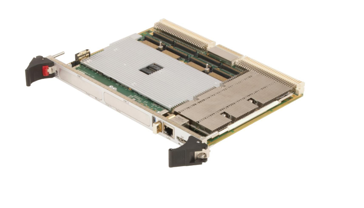
Abaco Systems’ XVR19 6U VME Single Board Computer (SBC) features the Intel

Xeon quad core processor (up to 8 MByte Last Level Cache) with error checking and

correction (ECC) support, integrated graphics and PCI Express (PCIe) channels. The

XVR19 is also equipped with Intel’s CM238 Chipset, supporting PCIe Gen 3.

allowing higher data transfer rates and more PCIe channels.  The CM238 chipset also

provides SATA, USB 3.0. graphic ports, SMBus, LPC and SPI design on the XVR19.

1.1  Features

• Single-slot 6U VME Single Board Computer

• Intel Xeon quad core processor

• Two channels of soldered DDR4 SDRAM with ECC up to 32 GByte

• Up to 8 MByte Internal CPU shared cache

• Up to 64 GBytes of BGA NAND SSD (Optional)

• Onboard Expansion Sites (supporting either XMC or PMC)

o

o

Site 1 (PMC rear I/O routed to P2)

▪ XMC1 – x8 PCIe

▪ PMC1 – PCI-X up to 64-bit

• 100 MHz (with option of two PMC sites)

• 133 MHz (with option of one PMC site)

Site 2 (PMC and XMC rear I/O routed to P0) – Optional

▪ XMC2 – x4 PCIe

▪ PMC2 – PCI-X up to 64-bit / 100 MHz

• Comprehensive range of front and rear I/O features:

1.1.1   Front I/O with only One Expansion Site:

• 2x Gigabit Ethernet ports via Intel I210

• 1x DisplayPort

• 3x USB 3.0 ports

• 1x COM port

• 1x Power button

• 1 x eSATA

1.1.2   Front I/O with Two Expansions Sites:

• 1x Gigabit Ethernet port via Intel I210

• 1x DisplayPort

• 1x USB 3.0 port

• 1x COM port

• 1x Power button

1.1.3   Rear I/O via Transition Module: (Option-Dependent)

• 2x Gigabit Ethernet ports

1x Gigabit Ethernet via Intel I219

1x Gigabit Ethernet via Intel I210

Publication No. 500-9300007879-000 Rev. T

16  XVR19 Hardware Reference Manual

• 2x Digital Video Interface (DVI-D)

• 4x SATA ports, Gen 2 capable

• 2x COM ports

• 2x USB 2.0 ports

• 8x General Purpose Input/Output (GPIO)

• 1x PMC rear I/O

• 2x Mezzio connectors (PMC/XMC)

NOTE

The VTM29 Rear Transition Module only supports the XVR19 in the environment specified for build level 1.

See level 1 details in Table A-3.

1.1.4   Other Features

• UEFI Flash and UEFI backup Flash

• Optional extended operating temperature range

• Three levels of ruggedization

The XVR19 offers two optional onboard mezzanine expansion sites for enhanced

system flexibility, PMC- and XMC- compatible.

Memory resources include up to 32 GByte DDR4 SDRAM and up to 64 GByte

NAND Flash drive.

Software choices include comprehensive Built in Test (BIT and OS 64-bit support for

Microsoft® Windows® 10. Fedora and Redhat Linux® and VxWorks®.

GE VMIVME-4150 Isolated 12-Channel 12-bit Analog Output Board with

Features

The VMIVME-4150 is a 12-bit Analog Output Board which provides 12þisolated high

quality 12-bit analog output channels on a single 6U form factor VMEbus board.  Each

channel is electrically isolated from all other channels and from the VMEbus.  Listed

below are some features of the VMIVME-4150 :

• 12 fully isolated analog outputs

• 1.000 Vpk isolation, channel-to-channel and channel-to-bus

• 12-bit resolution

• Bipolar voltage output ranges selectable as ±2.5.  ±5.  or ±10 V

• Unipolar voltage output ranges selectable as 0 to 2.5 V, 0 to 5 V, or 0þtoþ10 V

• 10 mA load capacity for voltage outputs over full ±10 V range

• Available with 4 to 20. 0 to 20. or 5 to 25 mA current loop outputs

• 0.05 percent accuracy for voltage outputs, 0.08 percent for current loop outputs

• 4. 8. or 12-channel configurations

• Optical data coupling provides full galvanic isolation

• Static readback data registers simplify program control

• Front panel access for field connections

• Program-controlled connect/disconnect operation of voltage outputs facilitates

system testing

Functional Description The VMIVME-4150 internal organization is illustrated in the functional block diagram shown in Figure 1.2-1. The board will operate with sustained isolation voltages as high as 1.000 Vpk. Bipolar output voltage ranges are selectable as ±2.5. ±5. or ±10þV. Unipolar output voltage ranges are selectable as 0 to 2.5 V, 0 to 5 V, or 0þtoþ10þV, and full 10þmA loading is supported throughout these ranges. 4. 8. or 12 channel configurations are available. Voltage outputs may be disconnected under program control during system testing, and are disconnected automatically during reset. Optional current-mode outputs support applications that require standard 4 to 20. 0 to 20. or 5 to 25 mA analog current loops. Compliance of the current mode outputs is 9 V if the loop supply originates on the board, or 27 V with an external loop power supply. A front panel LED (Fail) is provided. The LED light is on during system reset and can be turned OFF under user software control.

Search for products

Back to Top
Product has been added to your cart
phone: +86 18150137010
to whats
+8618150137010
to whats
+8618150137010
email: industrialists.yan@gmail.com