Call us 24/7+86 18150137010
Welcome to Industrial Control Trading Co., Ltd. Email: itadcs@163.com Whatsapp:+86-17750137010
Call us 24/7+86 18150137010

Yaskawa CP-317/DO-01 Digital Output Module

Yaskawa CP-317/DO-01 Digital Output Module

The YASKAWA CP-317/DO-01 Digital Output Module is designed for precise control in industrial automation applications.

It offers reliable performance and efficient operation, making it an ideal choice for various industries including manufacturing, automotive, and more.

Module Type:Digital Output Module

Model:CP-317/DO-01

Manufacturer:Yaskawa

Communication Interface:Built-in relay outputs

Output Channels:16 channels

Rated Voltage:24V DC

Current Rating per Channel:0.5A

Protection Rating:IP20

Operating Temperature Range:-10°C to +60°C

Dimensions:110mm x 80mm x 50mm

Weight:0.5kg

CP-317DO-01

The YASKAWA CP-317/DO-01 is meticulously designed to deliver consistent and dependable performance in industrial automation applications.

With its robust construction and precise engineering, it ensures long-term reliability and minimal downtime.

This module supports up to 8 channels of digital output, each capable of handling up to 0.5 A of current. The output voltage is 24V DC, making it suitable for a wide range of industrial devices and machinery.

CP-317DO-01

The CP-317/DO-01 features a compact design that allows for easy installation in tight spaces without compromising on performance or functionality.

Its operating temperature range from -10°C to +60°C ensures it can withstand harsh environmental conditions.

The module’s low power consumption and lightweight design contribute to energy efficiency and reduced maintenance costs.

Additionally, its simple yet effective design makes it user-friendly and easy to integrate into existing control systems.

Designed for seamless compatibility with other YASKAWA products and third-party equipment, the CP-317/DO-01 enhances the flexibility and scalability of your automation system.

Whether you are upgrading an existing setup or building a new one, this module is a valuable addition to your industrial control infrastructure.

Yaskawa CP-317/218IF High-Speed System Controller

Yaskawa CP-317/218IF High-Speed System Controller

The Yaskawa CP-317/218IF is a high-performance integrated controller part of the Control Pack (CP) and CP-9200SH series.

It is designed for large-scale industrial systems requiring rapid sequence control and sophisticated motion synchronization.

The model name refers to the combination of the CP-317 CPU module and the 218IF communication interface, which provides Ethernet connectivity.

This allows the controller to act as a master station for complex manufacturing plants, coordinating between multiple sub-controllers, HMIs, and engineering workstations.

Technical Parameter Table

ParameterSpecification
ManufacturerYaskawa Electric (Japan)
ModelCP-317 (CPU) with 218IF (Communication)
Processor32-bit High-speed RISC Processor
Scan MethodConstant-period scanning (High-speed & Low-speed levels)
Scan Time Setting1 ms to 300 ms (Units of 0.1 ms)
Program MemoryLarge capacity (Up to 512k steps in some revisions)
Communication (218IF)Ethernet (10/100 Mbps), Supports MEMOBUS/TCP
RedundancyECC (Error Check and Correct) memory & FPGA self-diagnosis
I/O CapacityExpandable via mounting bases (Up to 4 racks total)
Programming ToolMPE720 Engineering Tool (Ladder / SFC)

Product Advantages and Features

High-Speed Execution: Designed for complex arithmetic and high-speed motion synchronization, making it ideal for high-throughput production lines.

Open Networking: The 218IF module provides robust Ethernet communication, supporting standard protocols like MEMOBUS/TCP and Modbus/TCP for seamless integration with third-party software (SCADA/HMI).

CP-317/218IF

Fault Tolerance: Features ECC memory to automatically correct single-bit errors and detect multi-bit errors, ensuring system stability in environments with high electrical noise.

Backward Compatibility: Fully compatible with earlier CP-series hardware and software, allowing for easy upgrades of legacy systems without rewiring.

Multi-Level Programming: Supports hierarchical drawing (DWG) structures, enabling engineers to separate high-speed control tasks from background monitoring tasks.

CP-317/218IF

Application Cases

The CP-317/218IF is commonly found in “heavy” automation sectors:

Steel and Metallurgy: Controlling rolling mills and blast furnace charging systems where reliability and speed are paramount.

Water & Sewage Treatment: Serving as the master controller for wide-area distributed I/O systems in municipal infrastructure.

Automobile Assembly: Coordinating large robotic welding lines and synchronized conveyor systems.

Papermaking & Printing: Managing complex tension control and high-speed synchronization between multiple rollers.

Other Models in the Same Series

The CP series includes various CPU and interface combinations to suit different system scales:

CPU & Master Modules

CP-317M: The enhanced version of the CP-317 with higher memory and faster processing.

CP-3550: A high-end controller allowing up to four “virtual CPUs” in a single mainframe for parallel processing.

CP-9200SH: The overarching series name for these high-performance machine controllers.

Interface (IF) Modules

215IF: High-speed real-time core network (shared memory style).

217IF: Serial communication module (RS-232C / RS-422 / RS-485).

218TXB: A newer variant of the 218IF Ethernet module (Electrical/RJ45).

218FXB: Optical Ethernet variant for long-distance or high-noise communication.

Yaskawa CP-317/217IF Integrated Controller

Features:

Integrated Controller

Incorporates All Functions for General Machine Control

Optimum High Class Controller for Industrial Machinery

Performs High Speed Complete Synchronized Operation

The CP9200SH is an integrated controller which combines sequence control and motion control, incorporating all necessary functions for general machine control.

It is an optimum high class controller for industrial machinery which performs high speed, complete synchronized operation.

The modular design is organized into modules for each function.

The basic configuration consists of a power module, CPU module, and an SVA module.

Adding various types of other modules to this basic configuration makes it possible to expand your system.

Product Description

YASKAWA CP-317/217IF is a high-performance communication interface module engineered specifically for Yaskawa’s MP Series machine controllers, designed to enable seamless data exchange between controllers, HMIs, and external industrial devices in precision manufacturing and automation applications.

This module acts as a critical connectivity hub, supporting multiple industrial protocols to integrate Yaskawa’s motion control systems with third-party equipment such as PLCs, sensors, and SCADA platforms.

YASKAWA CP-317/217IF features a rugged industrial design with enhanced electromagnetic interference (EMI) protection, ensuring stable operation in harsh factory environments characterized by high vibration, temperature fluctuations, and electrical noise.

YASKAWA CP-317/217IF is fully compatible with Yaskawa’s MP3000/MP2000 controllers and MotionWorks software, allowing for plug-and-play integration and simplified system configuration without additional adapters.

CP-317217IF

Technical Parameters

Device Type: Communication Interface Module for Yaskawa MP Series Machine Controllers

Supported Protocols: Ethernet/IP, Modbus TCP/RTU, PROFINET IO, Yaskawa MECHATROLINK-III

Communication Ports: 2× Gigabit Ethernet ports, 1× RS-485 port, 1× internal MECHATROLINK-III port

Data Transfer Rate: Up to 1 Gbps (Ethernet), 100 Mbps (MECHATROLINK-III)

Operating Voltage: 24 V DC ±10%

Operating Temperature Range: -10°C to +60°C

Protection Rating: IP20 (cabinet-mounted installation)

Isolation: 2500 V AC between communication ports and controller logic

Compatibility: Yaskawa MP3000/MP2000 Machine Controllers, MotionWorks IEC Software, Yaskawa HMIs

Certifications: CE, UL, CSA, IEC 61131-2. RoHS Compliant

Advantages and Features

CP-317217IF

Multi-Protocol Flexibility

YASKAWA CP-317/217IF supports a comprehensive range of mainstream industrial communication protocols, eliminating the need for protocol converters and enabling smooth integration with both Yaskawa and third-party automation equipment. This flexibility reduces system complexity and deployment costs.

High-Speed Real-Time Data Transmission

With Gigabit Ethernet and MECHATROLINK-III support, YASKAWA CP-317/217IF delivers ultra-low latency data transfer, critical for synchronized motion control applications such as multi-axis robotic systems and high-speed packaging lines.

Rugged Industrial Design

Equipped with EMI shielding and reinforced circuit boards, YASKAWA CP-317/217IF resists electrical interference from nearby motors and power equipment, maintaining stable communication even in high-noise factory settings. Its wide operating temperature range also suits diverse industrial environments.

Seamless Yaskawa Ecosystem Integration

Optimized for Yaskawa’s MP Series controllers, YASKAWA CP-317/217IF integrates seamlessly with MotionWorks software for one-click configuration, real-time diagnostics, and motion control parameter tuning. It also supports remote monitoring for predictive maintenance.

High Reliability and Durability

Built with industrial-grade components and a fanless design, YASKAWA CP-317/217IF has a mean time between failures (MTBF) of over 150.000 hours, ensuring long-term, maintenance-free operation in continuous production environments.

Application Cases

Robotic Assembly Lines: YASKAWA CP-317/217IF enables real-time communication between Yaskawa MP controllers and articulated robots, synchronizing multi-axis movements to achieve precise component assembly in automotive electronics manufacturing.

High-Speed Packaging Machinery: Integrated into Yaskawa-controlled packaging lines, the module connects motion controllers to sensors and conveyor drives, ensuring accurate product positioning and reducing packaging errors by 30%.

Semiconductor Manufacturing Equipment: Used in wafer handling systems, YASKAWA CP-317/217IF supports high-speed data exchange for ultra-precise motion control, meeting the strict accuracy requirements of semiconductor processing.

Yaskawa CIMR-M5D2018 VS-626M5 Spindle Inverter

Yaskawa CIMR-M5D2018 VS-626M5 Spindle Inverter

The Yaskawa CIMR-M5D2018 is a high-performance AC Spindle Drive belonging to the Varispeed-626M5 (VS-626M5) series.

1 Unlike general-purpose industrial drives, this model is a vector-controlled inverter specifically engineered for machine tool spindle applications.

It is designed to work in tandem with a power regenerative converter (such as the VS-656MR5) to return energy to the power line during motor deceleration, significantly improving energy efficiency.

Technical Parameter Table

ParameterSpecification
ManufacturerYaskawa Electric (Japan)
ModelCIMR-M5D2018 (Series: VS-626M5)
Capacity18.5 kW / 22 kW (Typical based on duty rating)
Input Voltage200V Class (DC Bus Input: 270–325 VDC)
Output Voltage3-Phase 0–230 VAC
Rated Output CurrentApprox. 75 A – 85 A (Varies by load profile)
Control MethodSine-wave PWM Inverter (Vector Control)
Speed Control Range40 rpm to maximum motor speed
Speed Regulation±0.2% or less of maximum speed
WeightApprox. 12.25 kg (27 lbs)

Product Advantages and Features

High-Precision Vector Control: Provides exceptional torque control and speed stability, which is critical for high-quality surface finishes in machining.

Energy Savings: When paired with a regenerative converter, it recycles braking energy back into the power grid rather than dissipating it as heat.

Compact Integration: Specifically designed for CNC cabinets where space is at a premium, featuring a high power-to-size ratio.

Wide Speed Range: Supports both low-speed high-torque cutting and high-speed finishing within a single spindle motor setup.

CIMR-M5D2018

Reliability: Includes thermal protection for the motor and drive, overcurrent/overvoltage prevention, and ground fault protection.

CIMR-M5D2018

Application Cases

The CIMR-M5D2018 is a standard component in high-end manufacturing environments:

CNC Machining Centers: The primary drive for main spindles in 3-axis and 5-axis milling machines.

Lathes & Turning Centers: Managing the heavy-duty start/stop cycles of turning spindles.

Grinding Machines: Ensuring constant surface speed regardless of the grinding wheel’s diameter change.

High-Speed Woodworking: Precise control of routers and shapers requiring rapid acceleration.

Other Models in the Same Series

The VS-626M5 series scales according to the kilowatt (kW) requirement of the spindle motor:

200V Class Models

CIMR-M5D23P7: 3.7 kW Small Capacity.

CIMR-M5D27P5: 7.5 kW Medium Capacity.

CIMR-M5D2011: 11 kW Capacity.

CIMR-M5D2015: 15 kW Capacity.

CIMR-M5D2022: 22 kW High Capacity (Step up from 2018).

400V Class Models

CIMR-M5N45P5: 5.5 kW.

CIMR-M5N4011: 11 kW.

CIMR-M5N4018: 18.5 kW.

Yaskawa CACR-HR10BB Multi-Function Position Controller

Yaskawa CACR-HR10BB Multi-Function Position Controller

The Yaskawa CACR-HR10BB is a high-performance AC Servo Drive (Servopack) belonging to the legacy HR Series.

1 It is defined as a general-purpose multi-function position controller that integrates Yaskawa’s software-based positioning control technologies.

This series was specifically developed for advanced Factory Automation (FA) and Flexible Manufacturing Systems (FMS).

The “BB” designation indicates it is a Base-Mounted Type, as opposed to the “AB” rack-mounted versions.2

Technical Parameter Table

ParameterSpecification
ManufacturerYaskawa Electric (Japan)
ModelCACR-HR10BB
Device TypeAC Servopack / Servo Drive
Mounting StyleBase-Mounted
Input Voltage3-Phase 200–230 VAC (+10% to -15%), 50/60 Hz
Output Voltage3-Phase 0–230 VAC
Capacity / Power1.0 kW
Rated Current7.6 A to 8.0 A (Approx. varies by revision)
Control SystemSoftware-based multi-function position control
WeightApprox. 6.0 kg to 6.9 kg
Operating Temperature0°C to +55°C

Product Advantages and Features

Integrated Positioning: Unlike standard speed-control drives, the HR series features a built-in position controller, reducing the need for high-level motion control hardware in some applications.

High Reliability: Built-in protection circuits prevent damage from overvoltage, overcurrent, abnormal regeneration, and voltage drops.

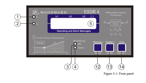
Maintainability: Includes a display function on the front panel to monitor status and troubleshoot via specific alarm codes.

Flexible Feedback: Compatible with Yaskawa’s precision optical encoders for high-accuracy positioning.

Dynamic Response: Optimized for quick response and stability even under adverse operating conditions or low-speed ranges.

CACR-HR10BB

Application Cases

The CACR-HR10BB is typically found in vintage and robust industrial machinery:

CNC Machine Tools: Precision control of feed axes in milling, turning, and grinding machines.3

Robotic Arms: Acting as the joint control drive for early-generation industrial robots requiring coordinated motion.

Injection Molding: Controlling the high-speed movements and positioning of molds and ejectors.

Textile & Printing: Managing high-speed synchronization in printing presses or textile weaving machines.

Automated Assembly: Used in dedicated assembly lines for electronics and semiconductor manufacturing.

Other Models in the Same Series

The CACR-HR series is divided by capacity (kW) and mounting style. Common variants include:

Capacity Variants (1-Axis)

CACR-HR05BB: 0.5 kW version.

CACR-HR15BB: 1.5 kW version.

CACR-HR20BB: 2.0 kW version.

CACR-HR30BB: 3.0 kW version.

CACR-HR44BB: 4.4 kW version.

Related Hardware

CACR-HRxxAB: Rack-mounted versions of the same controllers.

CACR-IR Series: Specifically designed for current command inputs (often used with older CNC controllers).

USA (M, F, G, S) Series Motors: The AC Servomotors typically paired with the HR10BB Servopack.

Woodward 8440-2052 easYgen-3200-5/P2 Genset Controller

Woodward 8440-2052: easYgen-3200-5/P2 Genset Controller

The Woodward 8440-2052 is a high-performance, versatile generator set controller belonging to the easYgen-3000 series (specifically the easYgen-3200-P2 model).

1 It is designed to manage complex power generation systems, providing comprehensive control, protection, and peer-to-peer paralleling for up to 32 generator sets.2

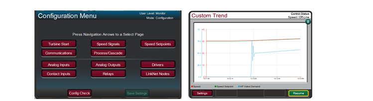
As a “Package 2” (P2) model, it includes an integrated HMI with a color display and three additional freely configurable PID controllers for advanced process automation.3

Technical Parameter Table

ParameterSpecification
ManufacturerWoodward
Part Number8440-2052 (Model: easYgen-3200-5/P2)
Power Supply12/24 VDC (Operating range: 8 to 40 VDC)
Intrinsic ConsumptionMax. 17 W
Current Inputs5A CT (Current Transformer)
Voltage Measuring100 VAC and 400 VAC (Configurable up to 650,000 VAC primary)
DisplayIntegrated Color LCD with soft keys
I/O CapacityUp to 12 Discrete Inputs / 12 Discrete Outputs (Configurable)
Analog Inputs3 Freely Scalable (0–2000 Ω, 0–1V, or 0–20 mA)
CommunicationCAN (J1939/CANopen), RS-485, RS-232, Modbus RTU
Operating Temp-20°C to +70°C

Product Advantages and Features

Integrated LogicsManager™: Built-in programmable logic allows users to create custom control sequences, often eliminating the need for an external PLC.4

Advanced Paralleling: Supports load sharing and synchronization for up to 32 units in island mode or parallel with a utility grid.5

True RMS Sensing: High-precision voltage and current monitoring (Class 1 accuracy) ensures stability even in systems with high harmonic distortion.6

FlexIn™ Technology: Analog inputs are highly flexible, supporting various resistance sensors and mA signals without extra hardware.

Multi-Lingual HMI: The operator interface supports 14 standard languages, making it ideal for global deployments.7

Robust Protection: Includes over/under voltage, frequency, and speed protection, as well as unbalanced load and phase rotation monitoring.8

Application Cases

8440-2052

The 8440-2052 is the “brain” for critical power infrastructure:

Data Centers & Hospitals: Managing emergency standby power with Automatic Mains Failure (AMF) detection and fast-start synchronization.9

Island Prime Power: Used in remote villages, oil and gas platforms, and mines to manage multiple gensets sharing a local grid.10

Cogeneration (CHP): Utilizing the three P2-specific PID controllers to manage heat recovery processes alongside electrical power production.

Microgrids: Integrating renewable energy sources with traditional diesel or gas generators for stable power distribution.11

8440-2052

Related Models & Series

The easYgen-3000 family consists of several variations based on mounting and feature sets:

Other Models in the Series

8440-2050 (easYgen-3200-5/P1): The “Package 1” version (standard features, no extra PID controllers).12

8440-2051 (easYgen-3100-5/P1): Back-panel mount version (no display/buttons on the unit).

8440-2082 (easYgen-3200XT): The newer XT series with enhanced processing and Ethernet communication.13

8446-1048 (RP-3000): Remote operator panel used to control easYgen units from a distance.14

Related Accessories

LS-5 Series: Circuit breaker controllers used for complex bus-tie management in multi-breaker systems.

ToolKit Service Tool: Woodward’s software used for configuration and real-time monitoring of the 8440-2052 via PC.15

Woodward PEAK200-HVAC 8200-1501 Digital Control for Steam Turbines

Peak200

PEAK200-HVAC  8200-1501

Digital Control for Steam Turbines

The Peak200 controller is designed to

operate small single valve, or single valve

rack industrial steam turbines. This cost

effective steam turbine controller includes

specifically designed algorithms and logic

to start, stop, control, and protect small

industrial steam turbines or turbo

expanders driving compressors, pumps, or

industrial fans.

The Peak200 control’s unique PID

structure makes it ideal for applications where it is required to control steam plant

parameters like turbine speed, turbine load, turbine inlet header pressure, turbine

exhaust header pressure, pump flow, or compressor discharge, or suction pressure.

The control’s special PID-to-PID logic allows stable control during normal turbine

operation and bumpless control mode transfers during plant upsets, minimizing

process over or undershoot conditions. The Peak200 controller senses turbine

speed via passive speed probes and controls the steam turbine through an actuator

connected to the turbine inlet steam valve(s). Peak 200 includes Woodward’s

patented adaptive PID controller that allows users automatic calculation for optimum

dynamic gains at their individual plant system.

Designed to function as a plant DCS node the Peak200 controller can be configured

to interface with the plant DCS via hardwired inputs/output signals or serial or

Ethernet communications. With the capability to monitor and control all turbine and

driven equipment based functions (i.e. bearing temperatures, vibration levels, control

oil levels, etc.) the Peak200 controller is ideal for use as a cost-effective turbine

control/protection as well as plant DCS monitoring node.

Alternatively the Peak200 can be configured to accept a remote turbine speed/load

demand from the plant DCS via a 4-20mA signal, discrete raise/lower commands, or

Ethernet or Serial Modbus communications.

PEAK200-HVAC 8200-1501

The Peak200 control also includes a special “Cascade” PID control function that can

be optionally configured and used to control any system process, related to or

affected by turbine speed or load. Typically, this controller is configured and used to

control turbine inlet header pressure, turbine exhaust header pressure, pump flow, or

compressor discharge, or suction pressure. The Cascade PID compares a 4–20 mA

process signal with an internal set point to directly position the Speed PID

controller’s setpoint, thus changing turbine speed or load until the process signal and

set point match. By cascading these two PIDs in this fashion, bumpless transfers

can be performed as well as turbine min/max.

Ethernet and serial communications allow users to easily connect the Peak200 in to

plant or process control system. All controller inputs, outputs, and statuses can be

monitored and all start/stop or enable/disable commands can be given through

industry standard Modbus TCP. The Peak200 uses SNTP (synchronized network

time protocol) over Ethernet to allow users to synchronize the Peak200’s real-time

clock to the plant distributed control system.

PEAK200-HVAC 8200-1501

The Peak200 control is available in either bulkhead models designed to be mounted on a wall or skid near the

turbine or panel-mount models designed to be installed within a standard panel or cabinet door. The product is

designed to meet NEMA 4x corrosion resistance tests and has an ingress protection rating of IP56. protecting it

against dust and water jets.

The control’s front panel serves as both a programming station and operator control panel (OCP). This user-friendly

front panel allows engineers to access and program the unit to the specific plant’s requirements, and plant operators

to easily start/stop the turbine and enable/disable any control mode.

Password security is used to protect all unit program mode settings. The controller’s 5” graphical display allows

operators to view actual and setpoint values from the same screen, simplifying turbine operation.

Turbine interface input and output wiring access is located on the controller’s lower back panel. Un-pluggable

terminal blocks allow for easy system installation, troubleshooting, and replacement. Optionally users can increase

the number of inputs and outputs signals to/from the Peak200 control by connecting LinkNet-HT distributed I/O

nodes to the controller’s CAN communication ports and configuring the Peak200 control to use the connected

distribute inputs and outputs. The following additional I/O signals can be connected to the Peak200 control via CAN

communications:

• (8) 4-20mA input channels and 2 4-20mA output channels (via 1 LinkNet-HT AIO module)

• (8) RTD signals (via 1 LinkNet-HT RTD module)

• (16) Discrete Inputs (via 1 LinkNet-HT DI module)

• (16) Relay output drivers (via 1 LinkNet-HT DO module)

Designed for steam turbine control, the Peak200 control includes two PID controllers (Speed & Cascade) multiple

startup routines (manual, automatic, remote control), and multiple protection functions (overspeed, critical speed

range, etc.) which can be configured by a user depending on the specific turbine application’s requirements. Users

can configure the Peak200’s different PID controllers, start routines, and protection levels themselves without the

need for a special control engineer. Once configured, the Peak200 performs a configuration check routine to ensure

that the programmer did not make any basic configuration mistakes.

Optionally users can utilize Woodward’s RemoteView software program with the Peak200 to function as a remote

operator control panel and or engineering station. This software program once loaded onto a remote computer or

touch panel, allows the user the following additional functionality:

• Perform the identical Peak200 front panel display functions (monitor, operate, tune, and configure) on the

respective computer or touch panel.

• Full function free for 2 hours

• Licensable for continuous GUI operation

• Password based login level security is utilized allowing function management for RemoteView applications

Refer to Woodward product specification B03424 for additional information.

The Peak200 includes a suite of service tools to allow users to perform the following functions:

• Upload configuration settings files from the Peak200 to save on another device

• Download configuration settings files to the Peak200

• View real-time or saved trend files

Control

• Dual dynamics (Speed PID)

• Adaptive speed/load PID dynamics

• Cascade PID (turbine/driven equipment pressures or

flows)

• Manual or auto start sequence

• First-Out indication (alarms & shutdowns)

• Peak speed Indication for overspeed trip

• Multi-lingual Display (English & Additional

Languages TBD)

• Remote analog setpoints for Speed/Load & Cascade

• Bearing temperature monitoring/alarms/trips

• Vibration monitoring/alarms/trips

System Protection

• Overspeed protection logic & test capability

• Critical speed band protection (1 band)

• First-out Indication (5 individual shutdown inputs)

• Bearing temperature alarm and trip settings

• Turbine vibration alarm and trip settings

• Control CPU & memory failure detection logic

• Mode login level password security

Cost-Effective Design— The Peak200 control is

designed to function as the turbine control, system

sequencer, operator control panel, and first-out indicator.

This encompassing design minimizes external system

devices as well as system installation, wiring, and

troubleshooting. This field configurable controller allows

major functional changes to be made at site, often by

knowledgeable plant personnel, and minor functional

changes to be online as process changes require. The

Peak200 control’s first-out-indicator logic indicates

internal as well as external system related alarm and

shutdown conditions, greatly simplifying and reducing

system troubleshooting.

Communications— The Peak200 controls can

communicate directly with plant Distributed Control

Systems and/or operator control panels, through two

Ethernet ports using Modbus TCP or UDP

communication protocols or via a serial Modbus port.

The Peak200’s serial port supports RS-232 or RS-485

communications using ASCII or RTU Modbus protocols.

Communications between the Peak200 and a plant DCS

can also be performed through hardwired connections.

Woodward 8237-1369 Speed protection

8237-1369

The 8237-1369 provides various pre-defined test routines including an automated periodic test routine to assist users with verifying system operation.

8237-1369 Technical Specifications

Dimensions    330 x 445 x 159 mm

Electromagnetic Compatibility    Emissions: EN61000-6-4 Immunity: EN61000-6-2

Enclosure Type    IP56 when installed correctly

Features    Reverse Polarity Protection for DC

High Input Voltage    Nominal 115 Vac / 240 Vac / 125 Vdc

Keypad/Display    15 Keys per module

Low Input Voltage    Nominal 24 Vdc

Operating Temperature    –20 to +60 °C (–4 to +140 °F)

Relative Humidity    Up to 95% (non-condensing)

Storage Temperature    –20 to +65 °C (–4 to +158 °F)

Weight    23 lbs before shipping

About the 8237-1369

8237-1369

Model 8237-1369 is an over speed detection device that can be configured to work with various turbines.

It is part of the ProTech-GII series from Woodward and fits any size of hydro, steam, or gas turbine.

In the event of over acceleration, this product will safely shut down the system.

Speed readouts for this device are between 4 and 20 mA, and it uses Modbus communication relays.

In addition to acceleration detection, model 8237-1369 also uses MPU detection.

This product performs routine tests to make sure each module is functioning properly.

A conformal coating material makes this speed safety device resistant to sulfur contamination, as well as H2S and SO2 gases.

8237-1369

Woodward ESDR 4 Current Differential Protection Relay

ESDR 4

Current Differential Protection Relay

The ESDR 4 is a three-phase current differential protection relay for generators and motors (protected object).

The currents flowing in the individual lines are each measured using a current transformer on both sides of the

protected object. They form the protection area boundary or zone. All two or three-phase short circuits and line

to-earth faults within this protection area are detected by the ESDR 4 as fault currents which initiate tripping.The

unit does not trip if fault currents occur outside the protection zone. In this way, a selective protection is guaran

teed.

The unit monitors six (6) measured currents via isolated inputs. The unit calculates internally the restraint current

(Is) and the differential current (Id) separately for each phase. The actual values of the calculated parameters (Dif

ferential current Id und Restraint current IS) are shown on the display either as absolute values or as a percentage

of the generator rated current (selectable in locked input mode).

ESDR 4

Theoretically the currents Ia and Ib are equal, both in fault-free operation and outside the protection zone (Figure

4-1-a).The difference is zero and the differential protection does not initiate. However, in practice current differ

entials do occur (= spurious currents), even in fault-free operation. They result, for example, from summation or

phase angle errors in the CTs, which are influenced by deviating burden values. These spurious currents remain

small inside the operating range, but increase with increasing load and are especially high when one or more CTs

become saturated (e.g. in the case of an external short circuit). In order to prevent a tripping of the relay due to

spurious currents, the trigger threshold is not held statically constant but increases in relation to the restraint cur

rent Is.  Spurious currents need to be taken into account when adjusting the trip characteristic.

When a fault occurs inside the protection area (Figure 4-1-b), unequal currents flow in the CTs, which result in a

current differential. If this exceeds the differential protection threshold, the relay will trip.

Monitoring of the Differential Current

ESDR 4

The monitoring of the differential current is carried out in two stages..

The first monitoring level serves as a warning and can be enabled or disabled. Should the adjustable warning

characteristic be exceeded, a text appears in the display and a relay contact is enabled. The pick-up time and the

dropout delay of the relay output are adjustable. The warning stage of the monitoring is auto-resetting.

The second stage of monitoring (main stage) serves to initiate tripping. In contrast to the first stage, it offers the

possibility to monitor the overstepping of an adjustable tripping characteristic (Id < In) and additionally, a fixed

tripping-threshold of 100%, relative to the generator rated current (Id > In). The trigger-delay for each limit value

may be independently adjusted, thus allowing a shorter triggering time at higher differential currents. When one

or both tripping characteristics are exceeded, a text display is initiated and two relay contacts are energized. The

tripping characteristics possess a 2% hysterisis relative to the generator rated current. .

The signal relay is only automatically reset if the function “automatic reset relay” in the Entry field on the screen

is configured to “on”. Otherwise, the resetting is carried out by pressing the “Clear” button on the front of the

unit or via the discrete input terminal 18 “reset”.

The two monitoring levels can also be used to change the characteristics of the control function (stage 1: small

value and a long time; stage 2: high value and a short time)

Tripping Characteristic

The following figure shows the tripping and warning characteristics (with sample values for X12. Y1.and Y2). It

represents the tripping and warning thresholds (Y) relative to the restraint current (X) The positions of the corner

points are determined by the coordinates P (X12/Y2) and P (X12/Y1). The selection of these positions is depend

ent on the generator being protected. The following gives the ranges of tripping and warning thresholds:

IS / IN

IS / IN

IS / IN

0 to X12

X12 to 5 × IN

> 5 × IN

The threshold Id is independent of the restraint current..

The threshold Id is dependent on the restraint current. A change of 100% in the

restraint current causes an increase of 10% in the tripping threshold.

The threshold Id stays constant at 85%.

Different characteristics can be chosen for the first and second monitoring levels, whereby the horizontal position

(X-coordinate) is valid for both stages. The vertical position (Y-coordinate) can be chosen separately for each

monitoring level. This results in a fixed difference in thresholds of the first and second monitioring levels for

each restraint current Is.

Control Inputs

Configuration

Terminal 17

Acknowledgement

Terminal 18

Blocking

Terminal19

Relays

Tripping (relay 1)

Terminals 1/2/3

Tripping (relay 2)

Terminals 4/5/6

Warning (relay 4)

Terminals 11/12/13

Ready for operation

(relay 3)

Terminals 7/8

When this input is energized, the unit locks into Configuration mode and stays in this

mode until the terminal is de-energized.

If this input remains energized for at least 1 s, the faults detected in monitoring

level 2 are reset. This means that the relays will be de-energized and the text display

will be deleted from the screen as long as the monitored currents are not exceeding

the configured threshold level.

When this input is energized, the differential protection is disabled.This means that

the differential current is not monitored, no relay can be enabled and no text is dis

played.

This relay becomes enabled when the unit detects threshold limit 2 (main stage) has

been exceeded. The configured differential current characteristics and delay time will

determine how relay 1 functions.

This relay becomes enabled when the unit detects threshold limit 2 (main stage) has

been exceeded. The configured differential current characteristics and delay time will

determine how relay 2 functions.

This relay becomes enabled when the unit detects threshold limit 1 has been ex

ceeded. The configured differential current characteristics and delay time will deter

mine how relay 4 functions.

This relay is enabled when the unit is operational and the differential current is being

monitored. The relay becomes disabled if the monitoring is deactivated through any

of the following reasons:

• the internal self-monitoring has detected a malfunction of the unit. A correct func

tioning of the unit cannot be guaranteed and corrective action may be necessary.

• the set values for parameter “CT-ratio” or parameter “Generator Current” are out

side the permissible limits (see page 19).

• the digital input “Blocking” is energized.

• the parameter “Monitoring” is configured to “Off”.

When in configuration mode (simultaneous pressing of “Digit↑” and “Cursor→”), the configuration screen can

be advanced by pressing the “Select” button. Should there be no entry, parameter change or other action for 60

seconds, the unit will automatically revert into Automatic mode.

During the configuration mode, the monitoring function is still active. This means inevitably, that while adjusting

parameters during operation, it is possible to cause a tripping of the relay.

adjust settings

[press “SELECT”]

Configuration mode “Select” button

Pressing the “Select” key activates the configuration mode, and the following pa

rameters can be enabled or changed within the given limits. Please you note that as

you advance through the configuration screens, by configuring some parameters as

“ON”, additional screens must be configured relating to that parameter. If the pa

rameter is configured as “OFF”, the additional screens will be disabled and not dis

played.

Software version

Software version

Displays the software version.

SPRACHE/LANGUAGE —————-

Language selection english/german

The screens can be displayed in German or English.

curr. transform.

ratio     0000/x

CT-Ratio Selection 10 to 6.000/{x} A

The Ratio of the CTs being used is entered here. The CTs should be selected so that

in fault-free operation at generator rated current, at least 60 % of nominal current

flows in the CT-secondary. Failure to use properly a sized CT-Ratio leads to loss of

resolution and inaccuracies in the monitoring functions.

generator nomin.

current    0000A

Generator rated current 5 to 6.000 A

This value is used as reference value for the calculation and display of restraint cur

rent and differential current. The entered value of generator current must be at least

60% of the nominal current of the CT and must not exceed the entered value of  CT

nominal current.

Example CT-Ratio 500/5 A

Range of Generator rated current 300 A to 500 A.

If the nominal value is less than 50% of the transformer ratio, the message “Wrong

Entry” will be displayed on the screen in Automatic mode and the unit will de

activate monitoring functions (the Monitoring LED goes out).

automatic reset

relay       ON

Automatic reset of the relay ON/OFF

Applies only to monitoring level 2 (tripping).

Monitoring level 1 (warning) always Auto-resets.

ON…………….The relays de-energize automatically when the fault is no longer pre

sent. The screen input “Automatic reset of error text” determines

what happens to the Alarm-text in the display.

OFF…………..The relays remain energized until they are reset.

monitoring

ON

Monitoring ON/OFF

ON…………….Monitoring of the differential current is active and the follow

ingscreens of this option are displayed.

OFF…………..The monitoring is de-activated and the following screens are not dis

played.

release limit

Is/In     X=000%

Trigger Value IS/IN (X12) 50 to 300 %

Definition of the threshold characteristic for the monitoring of levels 1 and 2.

This value determines the horizontal position (X12-coordinates of points

P [X12/Y1] and P [X2/Y2]) of the corner points of the Warning and Tripping char

acteristics.

release limit

Id/In     Y=000%

Limit valueId

This value determines the vertical position (Y2-coordinate) of the corner point

P [X12/Y2] of the tripping characteristic (monitoring level2).

pick-up t. Id>IN

release    0.00s

Relay enable delay time for Id>IN (monitoring level 2) 0.04 to 3.00 s

If the differential current surpasses the generator rated current without interruption

over this time period, a fault condition for exceeding the threshold limit will be ini

tiated.

pick-up t. Id<in< p=””></in<>

release    0.00s

Relay enable delay time for Id

If the differential current surpasses the adjusted trigger threshold without interrup

tion over this tme period, a fault condition for exceeding the threshold limit will be

initiated.

release time

release    0.00s

Relay disable delay time (monitoring level 2) 0.10 to 3.00 s

Only visible when the screen “Automatic reset of the relay” is configured to

ON .

If the differential current value which initiated the fault condition should fall 2% or

more below the trigger threshold limit and remain uninterrupted for the period of

time configured here, the fault condition will be terminated and the relay output

and the fault text will be reset.

automatic reset

error text   ON

Automatic reset of error text ON/OFF

Only visible when the screen “Automatic reset of the relay” is configured to

ON

ON…………….The displayed fault text will be automatically deleted, when the fault

conditions are no longer detected.

OFF…………..The displayed fault text must be deleted manually, and can only be

done when fault conditions are no longer detected.

automatic reset

error text   00s

Delay for automatic reset of error text 1 to 60 s

Only visible when the screens “Automatic reset of the relay” and “Automatic

reset of error text” are configured to ON

The fault text will automatically delete, when the fault conditions are no longer de

tected for the time period set here.

warning

ON

Warning (monitoring level 1) ON/OFF

ON…………….The adjustable warning characteristic is being monitored and the fol

lowing screens of this option are displayed.

OFF…………..The adjustable warning characteristic is not being monitored and the

following screens of this option are not displayed.

warning limit

Id/IN    Y=00.0%

Trigger value Id/IN (monitoring level1. Y1) 3.0 to 40.0 %

Only visible when the screen “Warning” is configured to ON.

This value determines the vertical position of the corner point of the warning char

acteristic. The horizontal position (X12) is identical with that of the trip character

istic. Usually the warning limit is lower than the trip limit value.

pick-up time

warning    0.00s

Enable delay time of the “warning” relay (monitoring level1) 0.04 to 3.00 s

Only visible when the screen “Warning” is configured to ON.

If the differential current exceeds the warning threshold curve without interruption

over this time period, the control recognizes that the warning limit has been ex

ceeded.

release time

warning    0.00s

Relay disable delay time (monitoring level 1) 0.10 to 3.00 s

Only visible when the screen “Warning” is configured to ON

If the differential current value which initiated the warning should fall 2% or more

below the trigger threshold limit and remain uninterrupted for the period of time

configured here, the fault condition will be terminated and the relay output and

fault text will be reset.

display value

Id           [-]

Display – measured value Id in [%] / [A]

[%]……………The percentage of the rated generator current that is measured is dis

played on the screen.

[A]:……………The measured absolute values are displayed on the screen.

display value

IS           [-]

Display – measured value IS in [%] / [A]

[%]……………The percentage of the rated generator current that is measured is dis

played on the screen.

[A]:……………The absolute measured values are displayed on the screen

Woodward easYgen-3000 Genset Control for

easYgen-3000

Genset Control for

Multiple Unit Operation

The easYgen-3000 is a control unit for genset management applications. The numerous inputs and outputs,

along with a modular software structure, permit you to use the easYgen-3000 for a wide range of applications

with only a single part number. This includes stand-by, AMF, peak shaving, import-export, cogeneration or

distributed generation, among others. Also the easYgen-3000 is compatible for island, island parallel, mains

parallel and multiple unit mains parallel operations.

The easYgen-3000 is able to control up to 32 gensets connected in a network with automatic sequencing.

The easYgen-3000 is available in two variants, the easYgen-3100 for cabinet back panel installation, and the

easYgen-3200 with graphical display and soft keys for front panel mounting.

FlexAppTM – This feature provides the tools to easily configure the number of operated breakers: None, GCB,

GCB and MCB.

LogicsManagerTM – Woodward’s LogicsManager software enables to change the operation sequences and

adapt them to specific needs. The LogicsManager accomplishes this by monitoring a range of measuring val

ues and internal states, which are combined logically with Boolean operators and programmable timers. This

enables to create and/or modify control and relay functions.

easYgen-3000

FlexInTM – The analog inputs are configurable to operate with VDO, resistive, and/or 0 to 20 mA senders.

Flexible Outputs – Speed and voltage bias outputs are configurable to function with all speed governors and

voltage regulators. The outputs can also be used as freely scalable outputs (e.g. for driving external meters).

FlexCANTM – Advanced network interfaces ensure unsurpassed control performance – from engine control up

to total plant operation. The easYgen-3000 is capable of working with all common industrial interfaces, includ

ing CAN, RS-232. and RS-485. The multiple communication protocols permit the easYgen-3000 to communi

cate with a vast majority of engine control units (ECUs), external I/O boards, PLCs, and modems. CANopen,

J1939. Modbus RTU, and Modem protocols are supported.

DynamicsLCDTM – The adaptive and interactive 5.7″, 320×240 pixel graphical LC display with soft keys and a

clear menu structure ensures intuitive user operation and navigation.

Features

easYgen-3000

• Operation modes: Auto, Stop, Manual, and Load/No Load test modes via discrete input possible

• Breaker control: Slip frequency / phase matching synchronization, open-close control, breaker monitoring

• Load transfer features: open / closed transition, interchange, soft loading / soft unloading, mains parallel

• Process and load-dependent start/stop logic for diesel and gas engines programmable for spinning or system

reserve with fixed or dynamic priorities.

• Real and reactive power load sharing with up to 32 units

• Remote control via interface and discrete/analog inputs for adjusting speed, frequency, voltage, power, reactive

power, and power factor set points

• Complete integrated engine and generator protection as well as mains monitoring features

• Freely configurable PID controllers for various control purposes, such as heating circuit control (CHP applica

tions), water level, fuel level, or pressure and/or other process values

• Special Scania S6. MTU ADEC, Volvo EMS2 & EDC4. Deutz EMR2. MAN MFR/EDC7. SISU EEM and Wood

ward EGS02 ECU support (depending on Package)

• Counters for operating hours / engine starts / maintenance / active energy / reactive energy

• Configurable trip levels / delay timers / alarm classes for monitoring and protective functions

• Clear text display and evaluation of up to 100 J1939 analog values

• Discrete and analog I/O expansion board connectivity (Woodward IKD 1 or Phoenix Contact IL series)

• Front panel and PC configurable (ToolKit software)

• Multi-level password protection for access via HMI or interface

• Multi-lingual capability (English, German, French, Spanish, Chinese, Japanese, Italian, Portuguese, Turkish, Russian)

• Peak shaving operation

• Stand-by operation

• AMF operation

• Cogeneration (CHP)

• Isolated & mains parallel

operation

• Import/export control

• Soft loading features

• Open/closed transition

• Load sharing and load

dependent start/stop for

up to 32 units

• Programmable operation

sequences

• Multi-lingual capability

• CANopen / J1939 ECU

Control

• Modbus RTU Protocol

• CE marked

• UL/cUL Listing

• LR & ABS Marine Ap

provals

• Event recorder (300 events, FIFO) with real time clock

Power supply …………………………………………………. 12/24 Vdc (8 to 40 Vdc)

Intrinsic consumption ………………………………………………………… max. 17 W

Ambient temperature (operation) ………………….. -20 to 70 °C / -4 to 158 °F

Ambient temperature (storage) …………………… -30 to 80 °C / -22 to 176 °F

Ambient humidity ……………………………………………… 95 %, non-condensing

Voltage ………………………………………………………………………………….. ( /Δ)

100 Vac [1] Rated (Vrated) …………………………………….. 69/120 Vac

Max. value (Vmax) ……………………………………. 86/150 Vac

Rated surge volt.(Vsurge) ……………………………………………. 2.5 kV

and 400 Vac [4] Rated (Vrated) …………………………………… 277/480 Vac

Max. value (Vmax) ………………………………….. 346/600 Vac

Rated surge volt.(Vsurge) ……………………………………………. 4.0 kV

Accuracy ……………………………………………………………………………… Class 1

Measurable alternator windings ………………… 3p-3w, 3p-4w, 1p-2w, 1p-3w

Setting range ………………… primary ……………………………50 to 650.000 Vac

Linear measuring range …………………………………………………….. 1.25×Vrated

Measuring frequency…………………………………………50/60 Hz (40 to 85 Hz)

High Impedance Input; Resistance per path ……. [1] 0.498 MΩ, [4] 2.0 MΩ

Max. power consumption per path ………………………………………… < 0.15 W

Current (Isolated) Rated (Irated) ………………………… [1] ../1 A or [5] ../5 A

Linear measuring range ………………………………………………. Igen = 3.0×Irated

Imains/ground = 1.5×Irated

Setting range ……………………………………………………………….. 1 to 32.000 A

Burden ……………………………………………………………………………… < 0.15 VA

Rated short-time current (1 s) ………………………….. [1] 50×Irated, [5] 10×Irated

Power ……………………………………………………………………………………………

Setting range …………………………………………………. 0.5 to 99.999.9 kW/kvar

Discrete inputs …………………………………………………………………… isolated

Input range ……………………………………………………. 12/24 Vdc (8 to 40 Vdc)

Input resistance …………………………………………………….. approx. 20 kOhms

Measuring

Generator voltage (3-phase/4-wire)

Generator current (3x true r.m.s.)

Mains voltage (3-phase/4-wire)

Mains or ground current (1x true r.m.s.) #1

Busbar voltage (1-phase/2-wire)

Control

Breaker control logic (open and closed transition) FlexAppTM 2   2   2   2

Automatic, Manual, Stop, and test operating modes

Single and multiple-unit operation

Mains parallel multiple-unit operation (up to 32 units)  #2

AMF (auto mains failure) and stand-by operation

Critical mode operation

GCB and MCB synchronization (slipping / phase matching)

Interchange (import / export control)

Load-dependent start/stop

n/f, V, P, Q, and PF remote control via analog input or interface

Load/var sharing for up to 32 gensets

Freely configurable PID controllers –   3   –   3

HMI

Soft keys (advanced LC display) DynamicsLCDTM –   –

Start/stop logic for diesel / gas engines

Counters for operating hours / starts / maintenance / active/reactive energy

Configuration via PC #3

Event recorder entries with real time clock (battery backup) 300   300   300   300

Protection ANSI#

Generator: voltage / frequency 59 / 27 / 81O / 81U

Generator: overload, reverse/reduced power 32 / 32R / 32F

Generator: unbalanced load 46

Generator: instantaneous overcurrent 50

Generator: time-overcurrent (IEC 255 compliant) 51

Generator: ground fault #4

50G

Generator: power factor 55

Generator: rotation field

Engine: overspeed / underspeed 12 / 14

Engine: speed / frequency mismatch

Engine: D+ auxiliary excitation failure

Mains: voltage / frequency 59 / 27 / 81O / 81U

Mains: phase shift / rotation field 78 /

I/Os

Speed input (magnetic / switching; Pickup)

Discrete alarm inputs (configurable) 10   10   10   10

Discrete outputs (configurable) LogicsManagerTM max. 12   max. 12   max. 12   max. 12

External discrete inputs / outputs via CANopen (maximum) 16 / 16   32 / 32   16 / 16   32 / 32

Analog inputs #5 (configurable)  FlexInTM 3   3   3   3

Analog outputs (+/- 10V, +/- 20mA, PWM; configurable)  2   2   2   2

External analog inputs / outputs via CANopen (maximum) –   16 / 4   –   16 / 4

Display of J1939 analog values (number of SPNs) 16   –   16   –

Display and evaluation of J1939 analog values (supported SPNs) –   100   –   100

CAN bus communication interfaces #6 FlexCANTM 2   2   2   2

RS-232/485 Modbus RTU Slave interface(s) 1 / 1   1 / 1   1 / 1   1 / 1

Listings/Approvals

UL Listing

cUL Listing

LR & ABS Marine Approval

CE Marked

Part Numbers

1A CT inputs / front panel mounting with display  #7 P/N 8440- –   –   1816   1842

5A CT inputs / front panel mounting with display  #7 P/N 8440- –   –   1831   1843

1A CT inputs / cabinet back mounting w/o display P/N 8440- 1818   1844   –   –

5A CT inputs / cabinet back mounting w/o display P/N 8440- 1817   1845   –   –

Spare connector kit P/N 8923- 1314   1314   1314   1314

Search for products

Back to Top
Product has been added to your cart
phone: +86 18150137010
to whats
+8618150137010
to whats
+8618150137010
email: industrialists.yan@gmail.com