Call us 24/7+86 18150137010
Welcome to Industrial Control Trading Co., Ltd. Email: itadcs@163.com Whatsapp:+86-17750137010
Call us 24/7+86 18150137010

GE Lentronics VistaNET Network Management System (NMS)

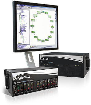
Lentronics™ VistaNET is a complete suite of software tools to securely manage the GE Vernova Lentronics family of telecommunications products, consisting of JungleMUX SONET and T1 Multiplexers, TN1U and TN1Ue SDH Multiplexers and E1 Multiplexers.

Key Benefits

  • Remote configuration, monitoring and testing of common equipment and service interface units minimizes disruption and maintenance costs
  • Simultaneous configuration and monitoring by more than one user distributes network administration and maintenance responsibilities
  • Time stamped logging and processing of alarms assists in identifying problems, facilitates alarm acknowledgement and provides immediate update on system status
  • Recording of network access and configuration changes provides accountability (an audit trail for future reference)
  • Single integrated system view for interconnected and discrete network segments simplifies management
  • Enhanced security through a multi-level password and privilege system with automatic expiration interval, controlled by a system administrator
  • Optical status information and BER statistics provide preliminary indications of system level problems
  • Encrypted databases and NMS communications help ensure system privacy
  • Optional SNMP agents to support network management (alarms, logs, inventory) by third party SNMP Manager
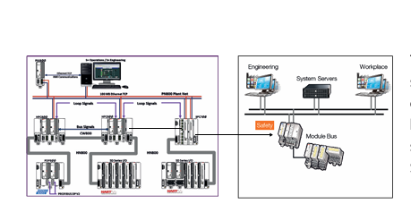
Network Visibility
  • Complete peer-to-peer NMS solution
  • Easily accessible through high speed corporate LAN/WANs and traditional dial-up systems
Centralized Management
  • Centralized management of contiguous and non-contiguous networks
  • Supports hundreds of nodes
  • Manages all Lentronics Multiplexers
Easy Accessibility
  • Intuitive, menu driven industry standard screens
  • Operates on standard Microsoft Windows platforms
  • Delivers complete monitoring information and configuration control
Cyber Security
  • Authentication of users and connected devices
  • Authorization of read/write privileges of each user
  • Accountability by logging alarms, events and user access
  • Privacy through encrypted NMS communications

VistaNET Components

  • VistaNET Local Access (VLA) is a low-cost, rudimentary NMS solution ideal for small networks
  • VistaNET Network Interface (VNI) is the standard NMS offering, providing remote configuration and monitoring
  • VistaNET Serial Communication Port Expansion is a Right to Use (RTU) license offered for each additional VNI serial communication port connection privilege (required when further redundancy is needed, or a new network segment is added)
  • VistaNET Server Application (VSA) provides a single instance RTU license for the VistaNET server gateway to run on a Windows 2008, NT, XP or 7 PC or LAN server computer. Expands VNI functionality from a remote VistaNET session over TCP/IP
  • VistaNET SNMP Agent (vSNMP) enhances VistaNET service with SNMP functionality, converting VistaNET alarms into SNMP traps and forwarding them to a user-defined list of SNMP managers. The agent supports Get commands of active and cleared alarms
  • VistaNET SNMP Agent (vSNMP Plus) includes vSNMP capabilities and adds an agent for External SNMP Management. Supports external GET commands to identify Network Topology, Inventory, Logs, and Datapoint Values. Executes external SET requests for rediscovery
  • Alternate Traffic Routing (ATR) provides a RTU license, enabling creation and activation of primary and backup traffic routing schemes in certain Lentronics optical transceiver units
  • VistaNET Traffic Manager (TM) shows current traffic usage and available traffic capacity and identifies physical port availability. Captures Inter- and Intra-node connectivity, inventory, and unit performance values, and then compares with historic values to determine inconsistencies

ABB System Controller Connect

System Controller Connect

New Ethernet based peer-to-peer

communication

Ethernet based communication

The System Controller Connect provides a dedi

cated, high speed, and secure interface between

Symphony Harmony/Symphony Plus systems and

800xA systems/safety systems.

Applications

The System Controller Connect software can be

used in applications requiring a:

• Fast and reliable interface between electrical and

process controllers

• Controller Connectivity for real-time data ex

change in mixed systems

• Interface between Symphony Harmony/S+ based

DCS controller and AC 800M High Integrity safety

controller

Overview

System Controller Connect is a software product

which is loaded and executed in a Symphony Har

mony/Symphony Plus controller.

System Controller Connect supports Manufacturing

Message Specification (MMS) protocol in the Sym

phony Controller. The  System Controller Connect

software is deployed as an MMS Client Application.

The AC 800M controller acts as a  Server and re

sponds to MMS commands sent from the System

Controller Connect client. The client application

reads/writes blocks of data in order to maximize ef

ficiency. This is accomplished by forming scan

The System Controller Connect

software provides a real time

dedicated and secure interface

between Harmony/Symphony Plus

systems and 800xA systems or

Safety systems.

groups containing a set number of access variable

values.

The System Controller Connect interface performs

non-SIL based communications that can be used for

‘high speed’ real-time data exchange communica

tion.

Features and benefits

• Transfer of 800xA tag values to the Symphony Har

mony / Symphony Plus system using MMS proto

col. MMS is a native protocol of the System 800xA

AC 800M controllers and thus needs minimal con

figuration effort and no additional hardware com

ponents.

• MMS access variables in the AC 800M controller

are supported in the user friendly interface. En

tries are defined as either read or write.

• Communication rates are fully tunable to meet re

quirements.

System 800xA values now available within the Har

mony blockware can be displayed in the Symphony

Harmony HMI.

System Controller Connect supports a fully redun

dant interface.  Redundant failovers are ‘bumpless’.

Redundant Ethernet address of the AC 800M con

troller using RNRP is fully supported.

Ethernet Module EI 803F ABB

Features

IEEE802.3 Ethernet standard

provides 10BaseT compliant communication (10MBit)

32-bit data bus

Transmission rate 10 MBit/s

Direct memory access to main memory, < 4% CPU over

head for operation

Optional battery for redundant battery backup of main

memory

Description

These communication modules provide Ethernet communica

tions to the system bus compliant with IEEE802.3 standard.

Communications module, compliant with 10BaseT shielded

Twisted Pair (STP, cable category 3. 4 or 5 advanced)

LED Displays

State

Off No supply voltage, module is isolated

Green Power supply on, module identified and

ready to operate as configured.

Orange Power supply on,

module identified and either:

— normal transitory state after module

startup

— configuration mode of Boot Loader

Orange flashing Power supply on, module identified; mod

ule not connected to proper bus structure.

Red Power supply on and either:

— module not yet identified (normal for

short time during module startup)

— error occurred during module test

Batt. Low

EI 803F

Off Sufficient buffer battery voltage.

Orange Buffer battery not found or low (insufficient

voltage).

EI 803F

Front Panel Connections

RJ-45 female connector (shielded).There are two integrated

LEDs indicating the current communication status. The LEDs

are not labeled but can be identified by their color. The upper

yellow LED indicates the link state, the lower green LED indi

cates active communication.

LED 10BaseT link

off No active link. No communication possible.

static yellow  Active link. Communication possible.

LED 10BaseT active

off No communication.

Technical Data

Rated voltage 3.3 V / 5 V, ±3%, from CPU board

Power consumption max. 1.8 W

STP 10BaseT cable category 3. 4 or 5 ad

vanced

RAM and real-time-clock buffering time

PM 802F  PM 803F

New battery inserted ≥ 1.5 years  without buffering

After “Low” warning ≥ 10 days

Battery 3.6 V lithium battery, 950 mAh

(not in the delivery)

Weight approx. 0.150 kg (without battery)

flashing green Active communication.

ABB Ethernet Modules EI 802F

Features

IEEE802.3 Ethernet standard

Provides 10Base5 compliant communication via AUI

32-bit data bus

Transmission rate 10 MBit/s

Direct memory access to main memory, < 4% CPU over

head for operation

Optional battery for redundant battery backup of main

memory

Description

These communication modules provide Ethernet communica

tions to the system bus compliant with IEEE802.3 standard.

Communications module, to connect a commercial transceiver

with AUI connector (15-pin female plug DIN 41652).

LED Displays

State

Off No supply voltage, module is isolated

Green Power supply on, module identified and

ready to operate as configured.

Orange Power supply on,

module identified and either:

— normal transitory state after module

startup

— configuration mode of Boot Loader

Orange flashing Power supply on, module identified; mod

ule not connected to proper bus structure.

Red Power supply on and either:

Page 10 June 2006

— module not yet identified (normal for

short time during module startup)

— error occurred during module test

Batt. Low

Off Sufficient buffer battery voltage.

Orange Buffer battery not found or low (insufficient

voltage).

Front Panel Connections

15-pin SUB-D socket with slide lock for AUI interface

Technical Data

Rated voltage 3.3 V / 5 V, ±3%, from CPU board

Power consumption max. 6.2 W (3 W + PIN Transceiver)

Full Ethernet 10Base5 via AUI/10Base5 transceiver

and AUI connection

EI 802F

Fiber optic cable 10BaseFL via AUI/FO transceiver and

AUI connection

Transceiver feeding

Rated voltage 12 V, ± 5%

Current requirement typ. 250 mA

RAM and real-time-clock buffering time

PM 802F PM 803F

New battery inserted ≥ 1.5 years  without buffering

After “Low” warning ≥ 10 days

Battery  3.6 V lithium battery, 950 mAh

(not in the delivery)

Weight  approx. 0.150 kg (without battery)

EI 802F

ABB Ethernet Modules EI 801F

Ethernet Modules EI 801F

Features

IEEE802.3 Ethernet standard

Provides 10Base2 compliant communication

32-bit data bus

Transmission rate 10 MBit/s

Direct memory access to main memory, < 4% CPU over

head for operation

Optional battery for redundant battery backup of main

memory

Description

These communication modules provide Ethernet communica

tions to the system bus compliant with IEEE802.3 standard.

Communications module, compliant with 10Base2 (Cheapernet)

for thin coax cable installations.

EI 801F

LED Displays

State

Off No supply voltage, module is isolated

Green Power supply on, module identified and

ready to operate as configured.

Orange Power supply on,

module identified and either:

— normal transitory state after module

startup

— configuration mode of Boot Loader

Orange flashing Power supply on, module identified; mod

ule not connected to proper bus structure.

Red Power supply on and either:

— module not yet identified (normal for

short time during module startup)

— error occurred during module test

Batt. Low

EI 801F

Off Sufficient buffer battery voltage.

Orange Buffer battery not found or low (insufficient

voltage).

Front Panel Connections

Coax connector

Technical Data

Rated voltage 3.3 V / 5 V, ±3%, from CPU board

Power consumption max. 2.8 W

Thin Ethernet 10Base2

RAM and real-time-clock buffering time

PM 802F PM 803F

New battery inserted ≥ 1.5 years  without buffering

After “Low” warning ≥ 10 days

Battery 3.6 V lithium battery, 950 mAh

(not in the delivery)

Weight approx. 0.150 kg (without battery)

ABB Power Supply SD 802F / SD 812F

Features

Input voltage 115 – 230 VAC (self adjusting), output is elec

trically isolated

Power supply outputs provide:

SA 801 F: 5 V DC / 5 A and 3.3 V DC / 5 A

SA 811 F: 5 V DC / 5.5 A and 3.3 V DC / 6.5 A

Enhanced power-fail prediction and shutdown procedures

LED indication for power supply status and operating

status of the AC 800F

SD 802F / SD 812F

Short circuit proof, current limited

20 ms backup energy for use in the event of primary power

failure, according to NAMUR

Description

The AC 800F modules are supplied with 5 V DC / 5 A and

3.3 V DC / 5 A auxiliary power by the SA 801F or 5 V DC / 5.5 A

and 3.3 V DC / 6.5 A by the SA 811F power supply. The power

supply has open-circuit, overload and sustained short-circuit

protection. The electronically controlled output voltage provides

high stability and low residual ripple.

In case of power loss ≥5 ms, the power supply module gener

ates a power-fail signal. This signal is used by the CPU module

to shut down operations and enter to a safe state. This is re

quired for a controlled restart of the system and the user appli

cation when power is restored. The output voltage remains

within its tolerance limits for at least another 15 ms. Altogether a

mains voltage drop of 20 ms will be managed.

SD 802F SD 812F

ABB Power Supply SA 801F / SA 811F

Features

Input voltage 115 – 230 VAC (self adjusting), output is elec

trically isolated

Power supply outputs provide:

SA 801 F: 5 V DC / 5 A and 3.3 V DC / 5 A

SA 811 F: 5 V DC / 5.5 A and 3.3 V DC / 6.5 A

Enhanced power-fail prediction and shutdown procedures

LED indication for power supply status and operating

status of the AC 800F

Short circuit proof, current limited

20 ms backup energy for use in the event of primary power

failure, according to NAMUR

Description

The AC 800F modules are supplied with 5 V DC / 5 A and

3.3 V DC / 5 A auxiliary power by the SA 801F or 5 V DC / 5.5 A

and 3.3 V DC / 6.5 A by the SA 811F power supply. The power

supply has open-circuit, overload and sustained short-circuit

protection. The electronically controlled output voltage provides

high stability and low residual ripple.

In case of power loss ≥5 ms, the power supply module gener

ates a power-fail signal. This signal is used by the CPU module

to shut down operations and enter to a safe state. This is re

quired for a controlled restart of the system and the user appli

cation when power is restored. The output voltage remains

within its tolerance limits for at least another 15 ms. Altogether a

mains voltage drop of 20 ms will be managed.

SA801F-SA811F

ABB Basic Unit PM 802F /PM 803F

eatures

Page 4 June 2006

Super Scalar RISC microprocessor (up to 150 MIPS)

16 K internal CPU cache RAM

RAM memory with error detection and correction

PM 802F: 4 MB static

PM 803F: 16 MB synchronous dynamic

Flash-EPROM

PM 802F: 4 MB, 32-bit words

PM 803F: 8 MB, 32- bit words

EEPROM, serial, 16 Kbit

Monitoring of the temperature inside the device

Watchdog

4 slots for fieldbus modules

2 slots for Ethernet communications modules, 32-bit data

bus, 100 MBytes/s

Battery backup incl. battery watchdog

Description

The basic unit, PM 802F and respectively PM803F, cyclically

scans signals from the fieldbus sensors via the corresponding

fieldbus modules, processes these signals according the appli

cation programs installed by the user and sends appropriate

signals to the fieldbus actuators via the fieldbus modules.

Controller redundancy can be achieved by installing two

AC 800F. To ensure quick and smooth takeover by the secon

dary AC 800F in case the primary AC 800F fails, a dedicated

redundancy communications link through the second Ethernet

module makes sure that both AC 800F are always synchro

nized. All inputs and outputs are designed to support redundant

operation.

Data communication between AC 800F, process and operator

stations runs over the Ethernet system bus on the first Ethernet

module. Data exchange with the engineering station is also car

ried via the system bus. Engineering station communications

can involve new or updated configuration files being

downloaded to the process stations, or information about the

connected modules being reported back. When fieldbus mod

ules are installed or exchanged, the required configuration in

formation is automatically updated.

Configuration and real-time process data is stored in RAM. To

safeguard this data in case of power loss, the RAM power is

backed up with batteries located either on the Ethernet modules

or on battery modules.

The PM 803F has more memory than the PM 802F and is

therefor capable to handle larger projects. Due to increased

memory size and different technology the buffering times were

reduced.

ABB AC 800F Controller Redundancy

AC 800F Controller Redundancy

Controller redundancy can be achieved by installing two

AC 800F. To ensure quick and smooth takeover by the secon

dary AC 800F in case the primary AC 800F fails, a dedicated

redundancy communications link through the second Ethernet

module makes sure that both AC 800F are always synchro

nized. All inputs and outputs are designed to support redundant

operation.

Profibus Line Redundancy

Using the Redundancy Link Module RLM 01 will do the conver

sion of one simple, non-redundant Profibus line into two recip

rocally redundant lines.

You can position the Redundancy Link Module RLM 01 directly

after a Profibus module (master), before a bus segment with

several slaves or before an individual slave. PROFIBUS sta

tions with redundant couplers can be directly connected to the

PROFIBUS set redundant by RLM 01. Stations with only one in

terface can be optionally assigned to the one or other line.

For technical description dates of the Redundancy Link Module

RLM 01 see document 3BDD011600R0201.

An alternative solution to the Profibus line redundancy is to use

a Fiber Optic Ring, for example with the OZD Profi 12M module

from firm Hirschmann

AC800F Redundancy together with Profibus Line Re

dundancy

You can achieve both; controller redundancy and Profibus line

redundancy by using two AC 800F with one RLM01 each. This

topology combines the advantages of controller redundancy

with the one of line redundancy as described in the above

paragraphs.

ABB Freelance800F AC800F Data Sheet

ControlIT is the

evolution of control

systems into

IndustrialIT:

Hardware and softwarecomponents seamlesslyintegrate process

oriented informationinto true openapplications,

improving processcontrol usingworldwide-accepted

industry standards.

Scalable and platformindependent productsshow the evolutionpath into the ITenvironment byenhancing your

installation.

AC 800F opens up the flexibility of Fieldbustechnology to the user.  The AC 800F collects

and processes diagnostic and process datafrom four Fieldbus lines, which may be of different types.  It does this in addition to thetasks of a “conventional” process station.

The AC 800F is available in two versions:

• 4 MB static RAM, 4 MB EPROM

• 16 MB synchronous dynamic RAM,

8 MB EPROM

Up to 4 (different) fieldbus modules can be

plugged into the AC 800F.  The communication

with other controllers runs via Ethernet.

The AC 800F optionally provides several levels

of redundancy:

• device redundancy with 2  AC 800F

• power supply redundancy (24 V DC)

• Ethernet communication redundancy

(standard)

• Cable redundancy for Profibus DP,

requires external equipment (RLM01)

The data protection is made via battery back-up

by Ethernet or battery modules with appropriate

AC800F

functionality.

• Process Station with integrated fieldbus

capability

• 4 high-speed fieldbus lines

• Supports different fieldbus types, even

simultaneously:

PROFIBUS-DP, up to 12 MBd

Modbus

CAN

Foundation Fieldbus H1 (with LD800

HSE)

• Easy engineering:

fully integrated in Control Builder F

• One unified database for field devices

shared by the control level and the Human

System Interface (HSI)

• Module recognition with factory and op

erational parameters

• Comprehensive diagnostics for proactive

maintenance

• Compact, rugged design

• Front panel connectors

• DIN Rail (C-rail) or wall mounting for easy

installation

• Ambient temperature 0-60 °C (32-140 °F)

with temperature monitoring

• EMC certification according to EN50082

• Certification:

CE, NAMUR, CSA, UL, EN61000-6-2.

AC800F

Search for products

Back to Top
Product has been added to your cart
phone: +86 18150137010
to whats
+8618150137010
to whats
+8618150137010
email: industrialists.yan@gmail.com