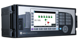
C60 Breaker Monitoring and Control / C95 Bay Control Unit for Substation and Industrial Automation
The C60 breaker and C95 bay controllers are a substation-hardened-devices that provide a complete integrated package for the protection, control, and monitoring of circuit breakers or bay. The C60 and C95 support dual-breaker busbar configurations such as breaker-and-a-half or ring bus arrangements. Signals from up to 4 sets of CT’s can be brought into the C60/C95 via conventional wiring or process bus for internal summation, which is advantageous by still having the individual currents available for metering and the additional protection elements that operate on individual currents.
Key Benefits
Complete breaker and bay control, monitoring and integration in a single platform
Advanced IEC 61850 Ed. 1 and Ed. 2 certified implementation, complete settings via SCL files and flexible process bus support (IEC 61850-9-2LE, IEC 61869 or IEC 61850-9-2 Hardfiber) ensures interoperability, device managing optimization and reduced cost of ownership
Routable GOOSE (R-GOOSE) enables GOOSE messages going beyond the substation, which enables wide area protection and control applications
Advance Cyber security features “CyberSentry™” that helps meet modern industry requirements
Phasor Measurement Unit (synchrophasor) according to IEEE® C37.118 (2014) and IEC® 61850-90-5 support
Supports latest edition of waveform capture (COMTRADE 2013) simplifying fault records management
Application flexibility with multiple I/O options including high density I/O, programmable logic, modularity, and specific customization
An integrated large, full color display, provides real-time visualization and control of the protected bay, via a bay mimic as well as annunciator functionality and graphical visualization of phasors
Applications
Stand-alone breaker or bay monitoring and control
Multiple breaker configuration control including breaker-and-a-half and ring bus
Automatic bus transfer scheme using a single device
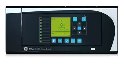
GE’s MiCOM C264 bay controller provides flexibility, reliability and ease of use. A combination of dual redundant fiber optic Ethernet, modular I/O, and an expandable design and extensive library of functions make the C264 the ideal solution for a wide array of applications in substation digital control systems.
Key benefits:
Flexible, modular, expandable design that supports many applications
Suitable for retrofitting and modernizing existing installations
Provides legacy and cutting edge communication interfaces
LCD graphical display for user-friendly local control, monitoring and maintenance
Proven solution with more than 110.000 units installed worldwide
Seamless modernization of existing installations
The C264 provides seamless integration with existing substation assets, thanks to its flexible interfaces and native expandability. Its powerful processing, communication and configuration facilities make it the ideal tool for upgrading substation supervision, automation and maintenance.
Innovative real-time automation schemes
MiCOM C264 enables innovative automation schemes thanks to extremely fast (event driven) Programmable Scheme Logic (PSL) and robust Programmable Logic Control (PLC).
Optimized engineering
The multifunctional capabilities of the C264 optimize system engineering, as fewer devices result in less wiring, training and maintenance.
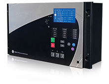
Substation hardened, the Multilin™ C650 has been designed to provide control, monitoring, and automation for a wide range of applications including bay control and monitoring in electrical substations. With high-density I/O capable of supporting up to 192 programmable digital inputs, the C650 can also be used to extend the I/O capability of new or existing protection and control relays. With powerful and deterministic programmable logic, advanced communications and metering capabilities ,the C650 is flexible, cost-effective and reliable solution for substation control.
Key Benefits
Flexible and deterministic programmable logic enabling customized substation automation and control schemes
Modular hardware enabling I/O expandability and configuration to meet application requirements
Advanced automation capabilities for customized control solutions
Reduced relay to relay wiring and associated costs with high-speed, inter-relay communications
Advanced communications including support for IEC 62439PRP/HSR and IEEE 802.1D/RSTP for increased network availability
Scalable I/O (up to 192 digital inputs or 48 digital outputs) providing application flexibility
Significant savings in installation costs with support for up to two remote CAN Bus IO modules
Extensive logic capability with high speed logic execution time
Applications
Bay control and substation automation for solidly grounded, high impedance grounded or resonant (Peterson Coil) grounded systems
Bus blocking/interlocking schemes
Throw over schemes (bus transfer schemes)
Load shedding schemes based on voltage and frequency elements or predefined shedding scenarios
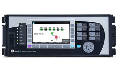
The C30 controller system is a programmable logic controller for performing substation or bay automation that can also be used for expanding the I/O capability of protection devices and replacing Sequence of Event (SOE) recorders. The C30 provides fast deterministic execution of programmable logic with I/O capabilities far above an average protection relay.
Key Benefits
Powerful, deterministic and very fast (2ms) programmable logic suitable for creating most customized automated substation control solutions
Advanced IEC 61850 Ed. 1 and Ed. 2 certified implementation, complete settings via SCL files ensures interoperability, device managing optimization and reduced cost of ownership
Routable GOOSE (R-GOOSE) enables GOOSE messages going beyond the substation, which enables wide area protection and control applications
Modular hardware architecture allowing for flexibility in the I/O configuration to support most bay management applications
Advance Cyber security features “CyberSentryTM” that helps meet modern industry requirements
Application flexibility with multiple I/O options including high density I/O, programmable logic, modularity, and specific customization
An integrated large, full color display, provides real-time visualization and control of the protected bay, via a bay mimic as well as annunciator functionality and graphical visualization of phasors
The VMIVME-4150 is a 12-bit Analog Output Board which provides 12þisolated high
quality 12-bit analog output channels on a single 6U form factor VMEbus board. Each
channel is electrically isolated from all other channels and from the VMEbus. Listed
below are some features of the VMIVME-4150 :
• 12 fully isolated analog outputs
• 1.000 Vpk isolation, channel-to-channel and channel-to-bus
• 12-bit resolution
• Bipolar voltage output ranges selectable as ±2.5. ±5. or ±10 V
• Unipolar voltage output ranges selectable as 0 to 2.5 V, 0 to 5 V, or 0þtoþ10 V
• 10 mA load capacity for voltage outputs over full ±10 V range
• Available with 4 to 20. 0 to 20. or 5 to 25 mA current loop outputs
• 0.05 percent accuracy for voltage outputs, 0.08 percent for current loop outputs
• 4. 8. or 12-channel configurations
• Optical data coupling provides full galvanic isolation
• Static readback data registers simplify program control
• Front panel access for field connections
• Program-controlled connect/disconnect operation of voltage outputs facilitates
system testing
Functional Description The VMIVME-4150 internal organization is illustrated in the functional block diagram shown in Figure 1.2-1. The board will operate with sustained isolation voltages as high as 1.000 Vpk. Bipolar output voltage ranges are selectable as ±2.5. ±5. or ±10þV. Unipolar output voltage ranges are selectable as 0 to 2.5 V, 0 to 5 V, or 0þtoþ10þV, and full 10þmA loading is supported throughout these ranges. 4. 8. or 12 channel configurations are available. Voltage outputs may be disconnected under program control during system testing, and are disconnected automatically during reset. Optional current-mode outputs support applications that require standard 4 to 20. 0 to 20. or 5 to 25 mA analog current loops. Compliance of the current mode outputs is 9 V if the loop supply originates on the board, or 27 V with an external loop power supply. A front panel LED (Fail) is provided. The LED light is on during system reset and can be turned OFF under user software control.
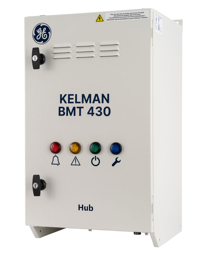
GE Vernova’s latest and advanced Kelman BMT 430 is on-line system that continuously monitors the condition of the bushings, which are constantly under high stress, and developing partial discharge (PD) activity in the transformer. It will immediately alert personnel of evolving fault conditions with the bushings and provide vital health information on the bushings and the transformer.
The Kelman BMT 430 is a standalone system but can also be easily integrated with a GE Vernova’s Kelman DGA 900 multi-gas analysis unit providing additional on-line DGA capabilities enabling a more in-depth view of the transformer’s overall condition and root cause of major transformer failures.
Key Benefits
One product monitoring bushing Capacitance, Power Factor (tan delta) and Partial Discharge activity using a single sensor and connection point.
Enhanced computing power, scalable I/Os and an integrated HMI combine to provide a powerful and reliable bushing monitoring solution.
Easily upgradeable in the field to a KELMAN DGA 900 Plus system for more in-depth and complete transformer monitoring package.
Full integration with GE’s acclaimed Perception™ Fleet asset management software.
One supplier installing, servicing, ensuring proper communication and minimizing administrative burden to lower the total cost of ownership of your transformer
System Features
System can monitor Monitors up to 3 sets of 3 bushings: 3-phase transformer or a bank of 3 single phase transformers.
Built-in web-page based HMI for easy and quick access to live measurements.
Integrated 7” color LCD screen for simplified local user interaction and visualization of data.
Extensive communication options for local and remote communications.
Inputs and outputs for additional sensors including load and top oil temperature.
Bushing Adaptor Features
Designed to allow off-line testing of bushing without completely removing bushing adaptor from voltage tap.
Marine grade aluminum to withstand extreme environmental conditions rated IP66.
Surge protection -suppression circuit to always limit voltage within the adapters in case of transients.
Fail safe circuit ensure the bushing tapping points remain grounded should open circuit and/or surge protection fail.
Benefiting from decades of transformer manufacturing experience and previous transformer monitoring systems (MS 2000), GE now offers the MS 3000 online condition monitoring and expert system.
The MS 3000 system provides a holistic approach that not only relies on a GE’s Dissolved Gas Analysis (DGA) monitor but expands the monitoring by connecting to the other existing transformer sensors and adding functionalities and measuring devices as per customer requirements.
It is a modular system that can cover the active part of the transformer but also the bushings, the cooling system, the on-load tap-changer and detect transient over voltages and the presence of partial discharge. It gathers all this data, detects any worrying trend and cross correlates the information to confirm the diagnostic and helps you assess your transformer’s health.
The MS 3000 includes a user-friendly web-based interface. It computes mathematical models based on IEEE/IEC standards to deliver valuable operational information and has a build-in simulator and an expert system software that provides operational recommendations in case of alarms. All this information is available remotely through a wide range of communication methods and protocols (including IEC 61850).
The MS 3000 is an “all-in-one” monitoring solution ideally suited to critical transformers, when enhanced coverage of potential causes of failure is required to provide peace of mind.
Bushing Monitoring and Partial Discharge Detection for Transformers
Bushings account for a large proportion of High Voltage (HV) substation failures, often causing severe and costly damages. Preventive maintenance, early replacement and regular off-line testing have been employed to address this issue in the past. Now, technology exists that enables asset owners to detect impending failures and reduce their maintenance costs.
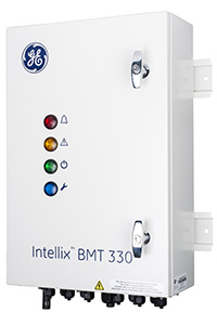
GE’s advanced Intellix™ BMT 330 is an on-line system that continuously monitors the condition of the bushings and can also detect developing partial discharge (PD) activity in the transformer main tank. It will alert personnel of fault conditions at an early stage and provide vital health information on the bushings and the transformer.
The Intellix BMT 330 can be utilized as a standalone system to monitor bushing insulation and partial discharge activity, or as an integrated, one-sourced solution with GE’s Kelman TRANSFIX Dissolved Gas Analysis (DGA) multigas analyzer and Perception Fleet software to provide a more in-depth view of the transformer’s condition and root cause of major transformer failures.
Key Benefits
Comprehensive monitoring of transformer bushings and PD activity on a bank of single phase transformers
One product combining advanced on-line continuous bushing monitoring and partial discharge activity in the transformer main tank using the same bushing adapter
One diagnostic software, GE’s Perception™, used for bushing information, PD activity and DGA data analysis, resulting in familiar easy-to-use information
One supplier installing, servicing, ensuring proper communication and minimizing administrative burden in order to lower the total cost of ownership of your transformer
Integrated Solution
Monitors bushing conditions and detects PD activity in the main tank
Can monitor 2 sets of 3 bushings (single phase and three phase transformers)
One-source provider that installs and services the entire solution
Can be stand-alone or easily integrated with GE’s Kelman family of DGA multi-gas units
Provides a more comprehensive view of the transformer’s condition
Minimal False Alarms
Compensation for actual bushing temperature using oil and ambient temperature sensors
Discrimination against factors affecting and causing the same effect on all bushings
PD to humidity correlation factor using included humidity sensor
Bushing Adapter Protection
Bushing analysis and PD detection data obtained using a single sensor
Marine-grade aluminum to withstand extreme environmental conditions
Redundant resistors ensure the bushing tapping points remain grounded
Voltage and surge suppression circuit to always limit voltage from adapters
Intuitive Software
Familiar Perception software included for download and visualization of data
Easy-to-use individual transformer software that can be upgraded to simultaneously monitor multiple transformers
Flexible database/server options to accommodate user requirements
9 gas on-line DGA expandable with add-ons to a Transformer Monitoring System (TMS)
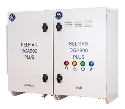
The Kelman DGA 900 PLUS is a member of the next generation of multi gas monitors. Built from the DGA 900 platform, the PLUS extends the monitoring capability beyond just DGA.
Knowledge of the condition of transformers is essential for all electrical networks and on-line monitoring of transformers is an increasingly vital component of successful asset management programs. The comprehensive information provided by the Kelman™ DGA 900 PLUS not only allows expensive failures to be avoided but enables asset capabilities to be maximized.
The Kelman DGA 900 PLUS builds on the standard 9 gas DGA and moisture capabilities of the DGA 900 by enabling the addition of extra sensors, electronic cards and firmware algorithms to expand its monitoring capabilities. Bushing monitoring, partial discharge detection, OLTC monitoring, transformer models are amongst the options available to offer an integrated system which delivers a more in-depth picture of the transformer’s overall condition and will monitor the root causes of most transformer failures.
Benefiting from over 15 years of multigas DGA vendor experience and over 15.000 devices in the field, the DGA 900 encapsulates learnings and improvements derived from its predecessors to bring improved performance, innovative new features, enhanced user experience and increased field reliability and robustness.
While on-line DGA is now widely accepted as the most effective method of assessing the condition of a transformer, it does not cover all the possible sources of issues. Subsystems like the tap changer, the cooling system or the bushings can generate their own problems if they are left unmonitored. The DGA 900 PLUS monitoring system integrates DGA measurement, additional sensors, analysis models and data handling features to address the majority of prevalent failure modes. This cost-effective package provides the condition assessment tools essential for the effective management and optimal utilization of this critical sub-station asset. It is most suited for monitoring large, mission critical transformers or compromised transformers with a view to extending their life and preventing any unexpected failure:
Key Benefits
Modular and retrofittable architecture using selectable standard add-on cards
Provides extensive remote insight into transformer condition and safe operation
Enables correlation of data for validation and in-depth fault analysis
Graphical presentation using built-in web-page based HMI and local color screen
Full integration with GE’s acclaimed Perception™ Fleet asset management software
From the only vendor with 15 years PAS experience and installed base of >15.000 units
Dissolved Gas Analysis (DGA) and moisture measurements of insulating fluids are recognized as the most important tests for condition assessment of transformers. In previous years, multi-gas DGA was traditionally confined to a laboratory environment, with infrequent yearly off-line manual sampling aiding time-based maintenance strategies
However, as the global average age of transformers continued to rise, the possibility of rapid aging and even catastrophic failure between off-line tests also increased, leading many asset owners to adopt on-line DGA monitoring to provides remote alert and multi-gas diagnostic of deteriorating transformer condition.
This facilitated operational decisions without needing to go to site for manual oil sampling. It avoided unplanned outages, increased network reliability and enabled the move to condition-based maintenance.
In the early 2000’s, GE’s original Kelman™ range of on-line multi-gas DGA analyzers brought Photo-Acoustic Spectroscopy (PAS) measurement technology to the market. GE is now proud to introduce the Kelman DGA 900. its next-generation multi-gas on-line DGA and moisture analyzer. At its heart lies an evolved implementation of GE’s proven PAS technology, providing laboratory challenging levels of precision and repeatability with no consumables (carrier or calibration gases) and no need for frequent re-calibration. It also has enhanced computing power and scalable I/Os for future proofing and adding functionalities to grow each analyzer into a flexible transformer monitoring solution.
Transformer issues can now be detected in their infancy, making sure that they are fixed early so that the nominal expected life of the transformer can be achieved. Maintenance interventions can now be planned, reducing their length and their cost and causing less disruption to the network and customers. In addition, aging asset replacement strategies can be anchored on hard health condition data and not purely based on the age of the transformer.
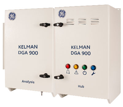
The Kelman™ DGA 900 is an 9-gas on-line transformer DGA monitoring unit. Using our 4th generation of advanced photo-acoustic detection technology, the DGA 900 measures all significant fault gases (in ppm) as outlined by international standards as well as moisture in oil (%RH & ppm). The measurement of these gases allows the user to detect and diagnose a complete range of transformer faults.
Benefits
Provides remote alert and multi-gas diagnostic of deteriorating transformer condition
Expedites operational decisions without needing to go to site for manual oil sampling
Issues can be detected in their infancy, avoiding unexpected failures and facilitating planned outages
Anchors condition based maintenance and asset replacement strategies on hard data
No need for consumables or frequent recalibration to operate at optimum performance
New “Rapid Mode” provides near real time insight on fast developing faults
Enhanced computing power, highly scalable I/Os and integrated HMI combine to provide a powerful highly flexible transformer monitoring solution
Compatible with mineral insulating oils and newer ester based fluids (natural and synthetic)
Features
DGA & Water – Nine gases (hydrogen, methane, ethane, ethylene, acetylene, carbon monoxide, carbon dioxide, nitrogen and oxygen) plus moisture
Inputs/Outputs for additional sensors including load and oil temperature
Full DGA results down to once per hour and new “Rapid Mode” for critical gases in just 30 minutes
Integrated 7” colour LCD screen for simplified local user interaction and visualisation of data
Innovative two enclosure design enables adjacent or separated installation arrangements to better accommodate varied site conditions
Communication Options – Extensive local and remote communications options