Mark V DS200 Series DS200DCFBG2BNCGBTC GE
Series: Mark V DS200
Part Number: DS200DCFBG2BNC
SKU: DS200DCFBG2BNCGBTC
About the DS200DCFBG2BNC
The DS200DCFBG2BNC is a Power Supply Board for the Mark V system from GE. The Mark V, which is one of the newest versions of the successful Speedtronic gas and steam turbine management system that has been developed by GE and released in various iterations since the late 1960s, relies on continued research and the use of the best technology available at the time of the system’s release to make improvements over previous systems. While the Mark V Turbine Control System Series may be one of the final General Electric Mark product series to utilize the Speedtronic control system technology, it must also be considered a now-obsolete legacy GE product series, considering its manufacturing discontinuation which took place in the many years following its initial release. This DS200DCFBG2BNC printed circuit board, although definable in its own right as a Mark V Series Power Supply Board, is by no means considered the original device of this Mark V Series functionality; that would be the DS200DCFBG2 parent Power Supply Board missing all three of this DS200DCFBG2BNC PCB’s three significant product revisions.
Hardware Tips and Specifications
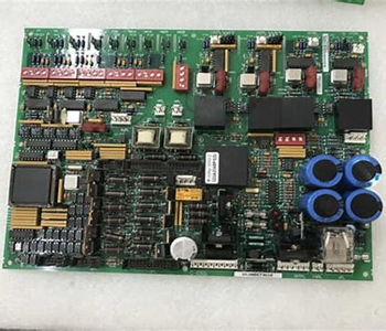
The DS200DCFBG2BNC sends and receives input and output signals via eighteen plug connectors and nine stab connectors. These connectors, along with the rest of this DS200DCFBG2BNC PCB’s specialized hardware, introduce this DS200DCFBG2BNC product to its intended functional role as a Power Supply Board. The stab connectors are located in the upper left corner of the board and are labeled V1 through V3, P1A, P2A, VM1A , VM1B, VB2A and VM2BA. The plug connectors are located throughout the board and range from male 2 pin connectors to multi-pin connectors. As this DS200DCFBG2BNC printed circuit board product offering from General Electric is attributable to a now-obsolete legacy product series, its originally-printed instructional manual materials are not available in large swathes online for the research purposes of this DS200DCFBG2BNC personalized product page. With this being true, the DS200DCFBG2BNC functional product number itself gains a new importance, as it details general DS200DCFBG2BNC Board hardware components and component specifications in a series of functional naming chunks. For example, the DS200DCFBG2BNC functional product number begins with the DS200 series tag dictating this DS200DCFBG2BNC Power Supply Board’s normal Mark V Series assembly as well as its domestic original manufacture location. Some of the other relevant hardware details revealed in the DS200DCFBG2BNC functional product number include this DS200DCFBG2BNC PCB’s:
DCFB functional product abbreviation
Normal PCB coating style
Group 2 Mark V Series product grouping
B-rated primary functional revision
N-rated secondary functional revision
C-rated artwork configuration revision
The DS200DCFBG2BNC is built with seven DIP switches, five TP test points, twelve jumpers, and three fuses. The fuses are for power supply protection. Indicators will light if any of these fuses are blown. These include two LED lights and one neon indicator. DIP switches are used to select AC line voltage and the voltage applied to the DC bridge voltage feedback VCO circuit as well as to the DC motor voltage feedback circuit. The DS200DCFBG2BNC is populated with various components, including seven transformers, oscillating chips, a relay, over fifty resistor network arrays, heat sinks, and various integrated circuits, capacitors, and resistors. The board uses CCR (carbon composite) resistors and resistors made of metal film material.Technical support for the DS200DCFBG2BNC was provided by GE. Please refer to manuals, data sheets or other publications for safety data relating to this part. Before making any ultimate purchase decision on this DS200DCFBG2BNC product offering, it is crucial to realize that its originally-introduced performance specifications and general dimensions have almost certainly been altered by its possession of a full three-fold revision history as outlined above.