Call us 24/7+86 18150137010
Welcome to the official website of Hong Kong Industrial Control Trading Co., Ltd.
Call us 24/7+86 18150137010

200-510-SSS-1Hh Vibro-Meter company VM600 system and sensor technical data

MPC4 machine protection card is the core component of the VM600 machine protection system of Vibro-Meter company.
This flexible card can measure and monitor four dynamic signal inputs and two speed/phase signal inputs at the same time. When the dynamic signal is input.
Fully programmable, can receive acceleration, speed and displacement signals or other signals. Multi-channel processing technology on the board can realize various physical measurements, such as relative
Shaft vibration, absolute shaft vibration, SMAX, eccentricity, shaft displacement, absolute and relative expansion, dynamic pressure, etc. The speed/phase input can be connected with various speeds.
Sensors (such as eddy current, reluctance, TTL, etc.) support fractional speed ratio.
MPC has powerful digital processing functions, including digital filtering, digital integration or differentiation, and digital modulation (root mean square, average, peak value, peak-to-peak value, etc.).
Frequency order tracking (amplitude and phase) and sensor gap measurement.
The output unit is set in metric or English software, and the alarm and shutdown values are completely programmable, including alarm delay, dead zone and maintenance. Alarm and shutdown can also be set.
It is defined as an adaptive function of speed or any other external information, which is used to automatically multiply the trip value of the unit when it passes the critical point.
Analog 0-10V or 4-20mA is optional, and it is output from the supporting IOC4T card. The switch value can be made use of the supporting IOC4T self-contained relay, or its
Its slot RLC16 and IRC4 relay cards output.
MPC4 card has self-checking function, and has built-in sensor OK monitoring and channel fault and alarm status monitoring, which can judge the sensor, preamplifier,
Cable failure, channel failure, alarm, etc., and displayed on the LED indicator on the front panel of MPC4.

Machine monitoring and protection module MPC4

Specifications–all MPC 4 cards

Dynamic signal input
Number of input signals: 4 signals per MPC4 card.
DC range: 0 to +20 V or 0 to −20 V.
AC range: 10 v (maximum)
Common mode voltage range: 50 to+50 V.
Cmrr: > 60 db at 50 Hz
Crosstalk: −72 dB
Input impedance: 200 kΩ
Current input range
Dc signal: 0 to 25 mA
Ac signal: 8 ma (max)
Analog AC frequency band
(without integration): 0.1 Hz to 10 kHz
Analog AC frequency band
(integration): 2.5 Hz to 10 kHz
Analog frequency band and
Other cards and buffered AC output: DC to 60 kHz (−3 dB)
Current detection resistance: 324.5

Processing options
bandwidth
Filtering options: Qualcomm, low pass or band pass.
LP/ HP passband ratio: 500 (maximum)
Fluctuation: 0.3 db
Slope: 6 to 60 dB/ octave (software configurable)
Outer passband attenuation: > 50 dB
Amplitude accuracy: 1% full scale
Linear error: < 1%
Equivalent input noise: < 200 µV RMS
(No integration)
Narrowband (tracking)
The MPC 4 card of “standard” and “independent circuit version” supports narrowband tracking, while the MPC 4 card certified by SIL does not support narrowband tracking.
Relative axis vibration
frequency band
Vibration: 0.1 Hz to 10 kHz
Clearance/position: DC to 1 Hz
Amplitude accuracy
Vibration: 1.2% full scale
Clearance/position: 1% full scale
Linear error: < 1%

GSI127 galvanic separation unit MEGGITT VIBRO-METER GSI 127 244-127-000-017 A1-B02 MODULE

KEY FEATURES AND BENEFITS 

• From the vibro-meter ® product line

• Power supply for sensors and signal conditioners with a current output or a voltage output 

• 4 kVRMS galvanic separation between the sensor side and the monitor side 

• 50 VRMS galvanic separation between the power supply and the output signal (floating output) 

• High rejection of frame voltage 

• µA to mV transfer function for current-signal transmission over longer distances 

• V to V transfer function for voltage-signal transmission over shorter distances 

• Ex certified for use in potentially explosive atmospheres (hazardous areas) 

• Compatible with industry standard IEPE (integrated electronics piezo electric) vibration sensors KEY BENEFITS AND FEATURES (continued) 

• Removable screw-terminal connectors 

• DIN-rail mounting 

• No ground connection needed APPLICATIONS 

• All vibro-meter ® measurement chains with current or voltage outputs 

• Safety-related applications DESCRIPTION The GSI127 is a galvanic separation unit from Meggitt’s vibro-meter ® product line. It is designed for operation with the signal conditioners, charge amplifiers and electronics (attached or integrated) used by various vibro-meter ® measurement chains and/or sensors.

DESCRIPTION (continued)

Compatible devices include the IPC707 signal conditioners (charge amplifiers) used by CAxxx piezoelectric accelerometers and CPxxx dynamic pressure sensors (and older IPC704 signal conditioners too), the IQS9xx signal conditioners used by TQ9xx proximity sensors (and older IQS4xx signal conditioners too), the attached or integrated electronics used by CExxx piezoelectric accelerometers, and the integrated electronics used by the VE210 velocity sensor. The GSI127 is also compatible with industry standard IEPE (integrated electronics piezo electric) vibration sensors, that is, the integrated electronics used by constant-current voltage output sensors such as the CE620 and PV660 (and older CE680, CE110I and PV102 sensors too). The GSI127 galvanic separation unit is a versatile unit that can is used for the transmission of high frequency AC signals over long distances in measurement chains using current-signal transmission or as a safety barrier unit in measurement chains using voltage-signal transmission. More generally, it may be used to supply any electronic system (sensor side) having a consumption of up to 22 mA.

The GSI127 also rejects a large amount of the frame voltage that can introduce noise into a measurement chain. (Frame voltage is the ground noise and AC noise pickup that can occur between the sensor case (sensor ground) and the monitoring system (electronic ground) ). In addition, its redesigned internal power supply results in a floating output signal, eliminating the need for an additional external power supply such as an APF19x. The GSI127 is certified to be installed in an Ex Zone 2 (nA) when supplying measurement chains installed in Ex environments up to Zone 0 ( [ ia ] ). The unit also eliminates the need for additional external Zener barriers in intrinsic safety (Ex i) applications. The GSI127 housing features removable screw terminal connectors that can unplugged from the main body of the housing to simplify installation and mounting. It also features a DIN-rail mounting adaptor that allows it to be mounted directly on a DIN rail. For specific applications, contact your local Meggitt representative.

SPECIFICATIONS

Environmental General Temperature •Operating :−40 to 70 °C (−40 to 158 °F) •Storage :−40 to 85 °C (−40 to 185 °F) Humidity (according to IEC 60068-2-30) •Operating : 90 % max. non-condensing •Storage : 95 % max. non-condensing Vibration (according to IEC 60068-2-6) : 1 g peak above resonant frequency and 0.15 mm peak below (5 to 35 Hz, 90 minutes /axis) Shock acceleration (according to IEC 60068-2-27) : 6 g peak (half sine-wave, 11 ms duration, 3 shocks/axis) Induced signal susceptibility (according to IEC 61000-4-4/5) :Performance criteria B RF susceptibility (according to IEC 61000-4-3) :Performance criteria A RF emissions – limits at 1 m (according to IEC 61000-4-3) :< 60 dBµV/ m (quasi-peak) from 30 to 230 MHz. < 67 dBµV/ m (quasi-peak) from 230 to 1000 MHz. Electrostatic discharge (according to IEC 61000-4-2) :Performance criteria B

https://static.websiteonline.cn/website/script/pdfjs/web/viewer.html?file=https%3A%2F%2Fpro7af9ac-pic10.websiteonline.cn%2Fupload%2FDS_GS3960.pdf&nodownload=1

VM600Mk2/ VM600 RPS6U rack power supplies vibro-meter

Блок питания VM600Mk2/VM600 RPS6U

Виброметр питания VM600Mk2 / VM600 RPS6U

KEY FEATURES AND BENEFITS

• From the vibro-meter ® product line 

• Power supply for VM600Mk2/ VM600 ABE04x 19 ″ system racks with a height of 6U 

• Input: AC-input and DC-input versions 

• Outputs: +5 VDC and ±12 VDC • Output over-voltage, short-circuit and overload protection 

• Status indicators 

• High-power, high-performance, high efficiency 

• Minimal derating within the operating temperature range

APPLICATIONS

• VM600Mk2/ VM600 machinery protection and/ or condition monitoring systems 

• One RPS6U rack power supply powers a full rack of modules (cards) 

• Two RPS6U rack power supplies enable rack power supply redundancy

DESCRIPTION

The VM600Mk2/ VM600 RPS6U rack power supplies are designed for use in the VM600Mk2/ VM600 series of machinery protection systems and condition and performance monitoring systems, from Meggitt’s vibro-meter ® product line. A VM600Mk2/ VM600 RPS6U rack power supply is installed in the front of a VM600Mk2/ VM600 ABE04x system rack (19 ″ system racks with a standard height of 6U) and connects via two high-current connectors to the VME bus of the rack’s backplane. The RPS6U power supply provides +5 VDC and ±12 VDC to the rack itself and all installed modules (cards) in the rack via the rack’s backplane.

DESCRIPTION (continued)

Either one or two VM600Mk2/ VM600 RPS6U rack power supplies can be installed in a VM600Mk2/ VM600 ABE04x system rack. A rack with one RPS6U power supply (330 W version) supports the power requirements for a full rack of modules (cards) in applications with operating temperatures up to 50 °C (122 °F). Alternatively, a rack can have two RPS6U power supplies installed in order to either support rack power supply redundancy or in order to supply power to the modules (cards) non-redundantly over a wider range of environmental conditions. A VM600Mk2/ VM600 ABE04x system rack with two RPS6U power supplies installed can operate redundantly (that is, with rack power supply redundancy) for a full rack of modules (cards). This means that if one RPS6U fails, the other will provide 100 % of the rack’s power requirement so that the rack will continue to operate, thereby increasing the availability of the machinery monitoring system. Note: This is known as a redundant RPS6U rack power supply configuration. A VM600Mk2/ VM600 ABE04x system rack with two RPS6U power supplies installed can also operate non-redundantly (that is, without rack power supply redundancy). Typically, this is only necessary for a full rack of modules (cards) in applications with operating temperatures above 50 °C (122 °F), where RPS6U output power derating is required. Note: Even though two RPS6U rack power supplies are installed in the rack, this is not a redundant RPS6U rack power supply configuration. The number and type of RPS6U power supplies installed in a VM600Mk2/ VM600 ABE04x system rack, together with the number of modules (cards) installed and the environmental conditions, helps determine the mode of operation of the RPS6U power supplies as either redundant or non-redundant. See also Ordering information on page 16. Different versions of the RPS6U rack power supply enable a VM600Mk2/ VM600 ABE04x system rack to be powered using external AC and/or DC mains supplies. All RPS6U power supplies support a wide input voltage range. A power supply check relay, available on the associated rear panel at the rear of a VM600Mk2/ VM600 ABE04x system rack, is used to indicate that the RPS6U power supplies are operating normally. Refer to the VM600Mk2/ VM600 ABE04x system rack data sheet for further information. In applications where the VM600Mk2/ VM600 ABE04x system rack is powered by an AC mains supply, a VM600Mk2/ VM600 ASPS auxiliary sensor power supply can also be included in the rack. The ASPS provides +24 VDC outputs which can be used by external sensor/measurement chain hardware such as front-end sensors, signal conditioners and galvanic separation units. For further information, contact your local Meggitt representative.

Notes 

 1. In 2016, the RPS6U rack power supply was improved to provide a higher output power of 330 W with higher-performance and higher-efficiency, which required a redesign of the underlying power supply circuitry. Accordingly, the different versions of the RPS6U rack power supply in use are: 

 • Later versions of the RPS6U (PNR 200-582-x00-02h or later) that define the power as a total maximum output power of 330 W,   with nominal output (supply) voltages of +5 VDC up to 50 A, +12 VDC up to 8 A and −12 VDC up to 4 A.   Note: The total maximum output power of 330 W is a combination load for all outputs as the +5 VDC and ±12 VDC outputs are   usually not simultaneously loaded to the maximum in practice. For example, if the +5 VDC output is at its maximum rated load   (5.35 V × 50 A = 267.5 W), then the combined loads on the +12 VDC and −12 VDC outputs must not exceed 62.5 W. 

 • Earlier versions of the RPS6U (PNR 200-582-x00-01h or earlier) that define the power as a rated power of 300 W,   with nominal output (supply) voltages of +5 VDC up to 35 A, +12 VDC up to 6 A and −12 VDC up to 2 A. 2. In 2021, VM600Mk2 (second-generation) machinery monitoring systems were launched with improved rack modules, notably the MPC4Mk2 + IOC4Mk2, RLC16Mk2 and CPUMMk2 + IOCNMk2. VM600Mk2 systems use the same system infrastructure as first-generation VM600 systems, that is, VM600Mk2 is backward compatible with existing VM600 (VM600Mk1) racks and power supplies. However, VM600Mk2 versions of the ABE040 system rack (PNR 200-040-100-016) and RPS6U rack power supplies (PNRs 200-582-200-12h, 200-582-500-12h and 200-582-600-12h) are also available. The VM600Mk2 versions are the same as the latest VM600 versions, except for the specific artwork/branding/finish. More specifically, the front panels of RPS6U rack power supplies are bare aluminium for the VM600Mk2 versions (PNRs 200-582-200-12h, 200-582-500-12h and 200-582-600-12h) and painted for the VM600 versions (PNRs 200-582-200-02h, 200-582-500-02h and 200-582-600-02h).

Environmental Temperature 

 •Operating 

 •Storage Humidity (according to IEC 60068-2-30) Vibration (according to IEC 60068-2-6) Shock (according to IEC 60068-2-27) Drop test (according to IEC 60068-2-31) MTBF (according to MIL-HDBK-217F) Conformal coating Indoor use Approvals Conformity Electromagnetic compatibility Electrical safety Overvoltage category Vibration Environmental management Russian federal agency for technical regulation and metrology (Rosstandart) : 0  to 70 °C (32 to 158 °F) : −40 to 85 °C (−40 to 185 °F) : 5 to 90 %, non-condensing : 10 to 55 Hz, 0.35 mm peak below resonance and 2 g peak above, 6 hours /axis : 6 g peak, 11 ms, half-sine pulse, 3 shocks /axis : 30 ° drop angle : > 40 000 hours at 70 °C (158 °F) : Applied to the circuitry of the power supply for additional environmental protection against chemicals, dust, moisture and temperature extremes : Limited to indoor use only : European Union (EU) declaration of conformity (CE marking). EAC marking, Eurasian Customs Union (EACU) certificate/ declaration of conformity. : EN 55022 class “B”. FCC Docket 20780 curve “B”. IEC 61000-4-2: Performance criteria B, 4 kV contact discharge and 8 kV air discharge. IEC 61000-4-3: Performance criteria A, 10V/m. IEC 61000-4-4: Performance criteria A, 2 kV 5/50 ns, 5 kHz, direct IEC 61000-4-6: Performance criteria A, level 3 IEC 61000-4-8: Performance criteria A, 50 Hz / 30 A / m TR CU 020/2011. : IEC / EN / UL / CSA 60950-1, 2nd edition. TR CU 004/2011. : OVC II : IEC 60255-21-1 (Class 2) : RoHS compliant (2011/65 / UE) : Pattern approval certificate OC.C.28.004.A N° 60224

VM600Mk2 MPC4Mk2 + IOC4Mk2 machinery protection modules vibro-meter

VM 600 MK 2 – mpc4mk 2 – ioc4mk 2 – виброметр

Вибраметр VM600Mk2 MPC4Mk2 + IOC4Mk2 Модуль механической защиты

KEY FEATURES AND BENEFITS

• VibroSight ® compatible hardware from the vibro-meter ® product line 

 • VM600Mk2 (second generation) machinery protection modules 

 • 4 dynamic channels and 2 auxiliary channels configurable as either tachometer inputs or DC inputs 

 • VM600Mk2 system safety-line to drive all system relays to a safe state 

 • Diagnostics (built-in self-test (BIST)) provides continuous feedback on the health of the modules 

 • Individually configurable inputs (with sensor power supply outputs), channel filters, processing and outputs – with simultaneous data acquisition (fixed frequency or order tracked) 

 • Up to 10 processed outputs per channel 

 • Multiple alarms per processed output with configurable limits, hysteresis and time delay 

 • AND, OR and majority voting logic functions for the combination of alarm and status information

KEY BENEFITS AND FEATURES (continued)

 • Discrete outputs: 4 user-configurable relays for use by alarms and 1 common circuit-fault relay 

 • Analog outputs: 4 outputs configurable as either 4 to 20 mA or 0 to 10 V 

 • Conforms to API 670 

 • Direct system Ethernet communications 

 • Compatible with VM600Mk2 system racks (ABE04x) and slimline racks (ABE056)

KEY BENEFITS AND FEATURES (continued)

 • Live insertion and removal of modules (hot-swappable) 

 • Software configurable

APPLICATIONS

• VM600Mk2 machinery protection (Q1 2021) 

 • VM600Mk2 machinery protection and/or condition monitoring (Q3 2021) 

 • Vibration and/or combustion monitoring 

 • API 670 applications

Introduction

The VM600Mk2 MPC4Mk2 + IOC4Mk2 machinery protection modules are designed for operation with the second generation of VM600Mk2 rack based machinery protection system (MPS), from Meggitt’s vibro-meter ® product line. The MPC4Mk2  + IOC4Mk2 are second generation modules (cards) that provide 4 dynamic and 2 auxiliary channels of machinery protection and basic condition monitoring in VM600Mk2 systems.

VM600Mk2 rack-based monitoring systems

The vibro-meter ® VM600Mk2 rack-based monitoring system is the evolution of Meggitt’s solution for the protection and monitoring of rotating machinery used in the power generation and oil & gas industries. VM600Mk2 solutions are recommended when a centralised monitoring system with a medium to large number of measurement points (channels) is required. It is typically used for the monitoring and/or protection of larger machinery such as gas, steam and hydro turbines, and generators, smaller machines such as compressors, fans, motors, pumps and propellers, as well as balance of-plant (BOP) equipment. A VM600Mk2 system consists of a 19″ rack, a rack power supply and one or more monitoring modules. Optionally, relay modules and rack controller and communications interface modules can also be included. Two types of rack are available: a VM600Mk2 system rack (ABE04x, 6U) that can house up to twelve monitoring modules, and a VM600Mk2 slimline rack (ABE056, 1U) that can house one monitoring module. The racks are typically mounted in standard 19″ rack cabinets or enclosures installed in an equipment room. Different VM600Mk2 monitoring modules are available for machinery protection, condition monitoring and/or combustion monitoring applications. For example, machinery protection modules such as the MPC4Mk2 + IOC4Mk2 modules, and condition monitoring modules such as the XMV16 + XIO16T monitoring modules for vibration and XMC16 + XIO16T monitoring modules for combustion. The RLC16Mk2 relay module is an optional module used to provide additional relays when the four user-configurable relays per set of MPC4Mk2 + IOC4Mk2 modules is not sufficient for an application. The CPUx  +  IOCx rack controller and communications interface modules (CPUM / IOCN and CPUMk2 + IOCMk2) are optional modules used to provide additional VM600Mk2 system functionality such as configuration management, “hot-swapping” with automatic reconfiguration (to be implemented for VM600Mk2), front-panel display, CPUx  +  IOCx modules redundancy, fieldbus data processing, front-panel alarm reset (AR) button, MPS rack (CPUx) security, system event and measurement event logging, fieldbus communications (Modbus, PROFIBUS and/or PROFINET) and/or communications redundancy. Note: Different versions of CPUx  +  IOCx rack controller and communications interface modules support different combinations of VM600Mk2 system functionality. VM600Mk2 systems are compatible with CPUMk2 + IOC Mk2 modules. VM600Mk2 rack-based monitoring systems complement the VibroSmart ® distributed monitoring systems that are also available from Meggitt’s vibro-meter ® product line, and are compatible with the same VibroSight ® machinery monitoring software suite.

MPC4Mk2 +  IOC4Mk2 machinery protection modules and VM600 racks

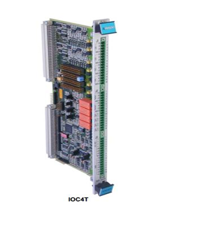
The MPC4Mk2 + IOC4Mk2 machinery protection modules monitor and protect rotating machinery as part of a VM600Mk2 rack-based monitoring system. The MPC4Mk2 module is always used with an associated IOC4Mk2 module as a set of modules. Both the MPC4Mk2 and the IOC4Mk2 are single width module that occupy a single VM600Mk2 rack slot (module position). The MPC4Mk2 is installed in the front of a VM600Mk2 rack and the associated IOC4Mk2 is installed in the rear of the rack, in the slot directly behind the MPC4Mk2. Each module connects directly to the rack’s backplane using two connectors. Note: The MPC4Mk2 + IOC4Mk2 modules are compatible with all VM600Mk2 racks (ABE04x system racks and ABE056 slimline racks) and later VM600 racks.

System communications

In a VM600Mk2 system (one or more MPC4Mk2 + IOC4Mk2 modules and any associated RLC16Mk2 modules), the main communications interface is the LAN (Ethernet) connector on the front panel of each MPC4Mk2 module, which is used for used for communication with the VibroSight ® software running on an external computer. In a VM600Mk2 rack (ABE4x), the VME bus can be used to share information between modules in the rack. For example, an MPC4Mk2 + IOC4Mk2 module can provide information such as measurement, alarm and/or status data to a set of CPUMk2 + IOC Mk2 modules which can then share the information via one of its industry standard fieldbuses. In a VM600Mk2 system (one or more MPC4Mk2 + IOC4Mk2 modules and any associated MPC4Mk2 modules), the RLC16Mk2 modules are controlled and operated by a MPC4Mk2 , as determined by the configuration. The VM600Mk2 rack’s Open collector (OC) bus and Raw bus are used to exchange control and status information between the MPC4Mk2 + IOC4Mk2 and RLC16Mk2 modules.

Relays

The MPC4Mk2 + IOC4Mk2 machinery protection modules include five relays. The four user configurable relays (RL1 to RL4) can be used by a VM600Mk2 system to remotely indicate system alarm and/or status information. While, a common circuit-fault relay (FAULT) is used to indicate a problem with the MPC4Mk2 + IOC4Mk2 modules as detected by the internal diagnostics (BIST). The relays in a VM600Mk2 system (specifically one or more sets of MPC4Mk2 + IOC4Mk2 modules and any associated RLC16Mk2 modules), are driven by control circuitry that supports a VM600Mk2 system safety-line, that is, a system-wide control signal that automatically drives all system relays ( IOC4Mk2 and RLC16Mk2) and analog outputs ( IOC4Mk2) to a safe state should a problem be detected. In this way, IOC4Mk2 and RLC16Mk2 relays configured as normally energised (NE) can always be de-energised in the event of a problem with one of the components of the relay coil control signal. Note: This supports the “de-energise to trip principle” required in safety-related applications.

Software

MPC4Mk2 + IOC4Mk2 modules, as part of a VM600Mk2  system), are software configured using the VibroSight ® software. To meet stringent cybersecurity and API 670 requirements, MPC4Mk2 + IOC4Mk2 modules segregate machinery protection (MPS) and condition monitoring (CMS) by using separate configurations and different VibroSight configuration software: 

 • VibroSight Protect supports the configuration and operation of the machinery protection (MPS) functionality for a VM600Mk2 system. 

 • VibroSight Capture supports the configuration and operation of the condition monitoring (CMS) functionality for a VM600Mk2 system. 

 • Other VibroSight software modules support operations such as data display and analysis (VibroSight Vision), data logging and post processing (VibroSight Server) system maintenance (VibroSight System Manager), etc.

DESCRIPTION (continued)

More generally for extended condition monitoring system (CMS) applications, the VibroSight software supports the configuration and operation of XMx16 / XIO16T modules for condition monitoring and/or combustion monitoring, including the processing and presentation of measurement data for analysis. VibroSight  is also used to configure and manage CPUMk2 + IOCMk2 modules. Note: The VibroSight ® software is also from the vibro-meter ® product line. Applications information As part of a VM600Mk2 system, MPC4Mk2 + IOC4Mk2 machinery protection modules are ideal for the monitoring and protection of critical assets such as gas, steam or hydro turbines and other high-value rotating machines in a wide range of industrial applications. For further information, contact your local Meggitt representative.


Our business is protecting yoursPower Generation, oil and gas production and distribution, petrochemical processing, gas turbine marine propulsion — these are typical areas where high-value,critical rotating machinery is employed. Safety has always been a major issue and protection systems, including vibratio parameters, are frequently mandatory. 

Main features and benefits Traditionally, separate systems have been provided for machinery protection, on-line condition monitoring, and machinery performance assessment. However, the VM600 Series uses the latest digital signal processing technology–and industry standard communications interfaces — todeliver the most up-to-date, integrated, modular, scaleabl solution to all machinery protection, condition and per formance monitoring requirements, within a single system framework. Only two types of signal processing modules are required — one for protection and one for condition and performance monitoring data acquisition. Each card can perform all of the necessary signal processing tasks, with input from any appropriate sensor, simplifying specification, installation, training and spares holding. 

¥ All monitoring functions (absolute and/or relative vibration, dynamic pressure, displacement, orbit, Smax, position, expansion, etc.) available on a single card

 ¥ Communications over Ethernet or serial links using standard protocols

 ¥ Remote configuration, interrogation and support

 ¥ Local display of levels and status

 ¥ Protection functions independent of condition monitoring functions

 ¥ API-670 compliant 

¥ Comprehensive voting logic combinations

 ¥ Cards are hot-swappable

 ¥ Dual redundant power supplies and communication links

 ¥ One 6U rack accommodates up to 48 protectionchannels or 192 condition monitoring/process inputs.

 ¥ “Platform independent” software –WindowsTM NT/2000,SCO Open Server (UNIX), Linux

DYMAC total system capability

 SENSORS & SIGNALCONDITIONING

 Afull range of industrial accelerometers, velocity transducers, eddy current probes, dynamic pressure sensors, air gap

 sensors, and ice detectors for high temperatures and other harsh environments.

 MACHINERYPROTECTION SYSTEMS

 Fully autonomous protection systems for instant detection of machinery problems. Protection for both excessive

 vibration and over-speed conditions. A single universal card accepts input from all dynamic and static sensors, and

 provides a comprehensive array of processing and voting logic, with analogue, DC and digital outputs to other systems. 

MACHINERYCONDITION MONITORING

 On-line and off-line hardware and software solutions for prediction of machinery problems in advance. Automatic high

speed detection of run-up/ coast-down and ’upset capture’ data, 16 channel parallel data acquisition cards, all dynamic

 and static inputs. Sophisticated Condition Monitoring software for machinery monitoring and analysis, including

 continuous streaming technology, logging by exception, interfaces to portable devices and DCS systems, and a full array

 of diagnostic tools such as Fast Fourier Transform (FFT). Remote access over modem, network or internet. Specialised

 applications including hydro turbines and reciprocating compressors.

 MACHINERYPERFORMANCE MONITORING

 Basic Package — manual or automatic data entry, simple performance calculations and trending of aero thermal

 parameters.

 Advanced package — automatic data entry, modelling refined with experience, comparison of actual against expected

 performance giving a true online picture of machinery behaviour for decision support.

 Maintenance Optimisation — fuel used, emissions, calculation of emission taxes, parts life calculation for hot com

ponents, predicted and measured calculation for maintenance actions

Lorem ipsum dolor sit amet, consectetur adipiscing elit. Ut elit tellus, luctus nec ullamcorper mattis, pulvinar dapibus leo.

Search for products

Back to Top
Product has been added to your cart
phone: +86 18150137010
to whats
+8618150137010
to whats
+8618150137010
email: industrialists.yan@gmail.com