I. Introduction Rolls-Royce is not only a top luxury car manufacturer, but also an important supplier of high-end industrial equipment and ship control system. Its display products are widely used in ship control, industrial automation and aviation, and are famous for their high reliability, accurate display and advanced technology. This paper will analyze the functional characteristics, technical advantages and application fields of Rolls-Royce display based on official data.
Second, the main features of Rolls-Royce display
High precision TFT display technology Rolls-Royce displays mostly use TFT (thin film transistor) LCD screen and are equipped with LED backlight technology to ensure clear and high-contrast visual effects in strong or weak light environment. For example:
P001240-1 display (115Vac/60Hz TFT) is suitable for ship control system, although some equipment may have fault reports. The 12.3-inch TFT color display (applied to Phantom models) adopts virtual pointer, precise calibration and high-resolution UI design to ensure that the data is intuitive and easy to read.
Multi-environment adaptability Rolls-Royce display supports wide voltage input (such as 115V/250V, 50/60Hz), which is suitable for different power standards around the world. Some models (such as UN925) also have anti-electromagnetic interference ability and are suitable for ships and industrial environments.
Intelligent interaction and integrated control In the automotive field (such as Spectre electric vehicle), the central touch screen of Rolls-Royce supports:
Wireless Android Auto/Apple CarPlay Voice control function HUD system provides driving information in real time. In the industrial field, some displays (such as Hatteland Display series) integrate PLC and I/O module for monitoring the ship propulsion system.
Modular and customizable design For example, P001240-1 Rev.2 and other models adopt modular structure, which is convenient for maintenance and upgrading. Some high-end models support customized UI interfaces to meet the operational needs of different industries.
Third, the application field
Ship and Ocean Engineering Rolls-Royce displays are widely used in ship control systems, such as:
Propulsion system monitoring (such as JH 20T04 MMD-A1-1043 display) Power management (e.g. display screen of H1127.0101 Marine Controller) These equipments should be waterproof and corrosion-resistant, and can run stably in bad sea conditions.
Industrial automation In the fields of manufacturing and energy, Rolls-Royce monitors are used for:
PLC control panel (such as 25300016C Digisound control panel) Hydraulic system monitoring (such as the display unit of M2202 three-cavity hydraulic motor kit)
High-end automotive and avionics In the automotive field, its display screen integrates navigation, driving assistance and entertainment systems (such as Spectre’s central touch screen); In the aviation field, similar technology may be used for avionics instrument display.
Fourth, summary Rolls-Royce display plays an important role in the fields of ship, industry and automobile with its high precision display, environmental adaptability and intelligent control. In the future, with the development of digitalization and AI technology, its display will further evolve in the direction of higher integration and more humanized interaction.
Rolls-royce rrdio 15 I/o alarm module is a digital input/output module, which is mainly used for monitoring and alarm system in shipbuilding industry. The module can receive and send digital signals in real time, which can be used to monitor and control various equipment and systems of ships, such as engines, propulsion systems, electrical systems, etc., and provide alarm function when faults occur, thus helping the crew to take timely measures to avoid potential risks.
The module has high reliability and durability, is suitable for extreme environment (temperature range:-40 C to+70 C), and meets the protection level of IP40, and can run stably under severe conditions such as high temperature, low temperature, vibration and salt spray. In addition, it also supports a variety of ship systems and equipment interfaces, which is highly integrated and flexible.
Rolls-royce RR Dio 15 I/O alarm module is widely used in large ocean-going oil tankers, cargo ships, passenger ships, marine engineering, port management and maritime rescue, and is the key equipment to improve the efficiency and safety of ship operation.
DEIF DLQ72-PC-PY Rolls-Royce K85240 pitch indicator is a high-precision instrument specially designed for ship navigation and control. Its main function is to provide accurate data of ship dynamic performance by measuring the pitch of propeller. This equipment is widely used in the field of navigation technology, especially in the ship propulsion system.
Rolls-Royce K85240 pitch indicator adopts advanced electronic technology, which can monitor and display the pitch change of propeller in real time. Pitch refers to the distance that the blades advance in the water when the propeller rotates, and it is one of the key parameters to measure the efficiency of the propeller and the dynamic performance of the ship. By accurately measuring the pitch, the crew can optimize the navigation state of the ship, improve fuel efficiency and ensure navigation safety.
The equipment supports 10V voltage input and is suitable for various ship environments. Its design conforms to international standards, has high reliability and durability, and can run stably in harsh marine environment. In addition, Rolls-Royce K85240 pitch indicator can also be integrated with other navigation systems, such as the XDi series LCD bridge instrument system of DEIF, and data sharing can be realized through NMEA interface. This integration ability makes the ship operation more intelligent and improves the cooperative efficiency of the overall navigation system.
Rolls-Royce K85240 pitch indicator is not only suitable for monitoring the ship propulsion system, but also can be used in other application scenarios that require accurate pitch measurement. For example, in the process of ship maintenance and debugging, the equipment can help technicians to quickly detect the performance of propellers and make necessary adjustments. In addition, it can also be used in the ship automatic control system to optimize the speed and course control of the ship by feeding back the pitch data in real time.
Rolls-Royce K85240 pitch indicator has become an important tool in the field of ship navigation and control because of its high precision, versatility and reliability. It can provide reliable performance data support for the crew and ensure the safe and efficient operation of the ship, whether in daily navigation or special tasks.
Rolls-Royce marine brand UN991.1 distribution board is a power distribution equipment specially designed for marine power stations. Its core function is to realize the distribution, control and protection of electric energy. As an important product of Rolls-Royce, the distribution board plays a key role in the ship power system, providing reliable power management solutions for ships. Rolls-Royce marine UN991.1 distribution board belongs to the automation series of controller platform, and its design meets the needs of modern ship power stations and can adapt to ship power stations with different voltage levels and operating conditions. According to the information I searched, distribution boards are usually divided into main distribution boards and emergency distribution boards, and UN991.1 distribution board may belong to one of them, which is used for the main distribution or emergency distribution function of ship power stations.
The main features of the UN991.1 distribution board for Rolls-Royce ships include: High reliability: As a part of Rolls-Royce brand, the distribution board inherits the professional advantages of Rolls-Royce in the field of ship electronics and automation, and has extremely high reliability and stability. Multifunctional integration: the distribution board is not only used for power distribution, but also integrated with monitoring and protection functions, which can monitor the running state of the power station in real time and automatically cut off the power supply to protect the equipment under abnormal conditions. Flexible configuration: according to the specific needs of ship power stations, the UN991.1 distribution board can be flexibly configured, including modules such as generator control panel, bus bar and various feed screens. Conform to international standards: the design and performance of the distribution board conform to the relevant international standards such as the Code for the Construction of Steel Seagoing Ships, ensuring its applicability in various complex ma
Rolls-Royce Terminology List Panel is a controller platform component specially designed for Rolls-Royce cars, and its product number is 000127697. This panel belongs to the technical equipment series of Rolls-Royce brand and may be used for electronic control or information display of vehicles. According to the description provided by the seller, this panel is in a brand-new unused state, which is suitable for users who need to maintain or upgrade the electronic system of Rolls-Royce vehicles.
As a luxury car brand, Rolls-Royce usually has high-end and sophisticated technical equipment. For example, the diagnostic training manual of Rolls-Royce CAN network bus system and the diagnostic training materials of infotainment system mentioned in, indicate that Rolls-Royce has adopted advanced technical architecture in vehicle electronic system. Therefore, the term list panel 000127697 may also be associated with these advanced technical systems to support electronic control and data management of vehicles.
Although the evidence does not directly mention the specific function of the term list panel, combined with the technical characteristics of Rolls-Royce and
The complex internal structure of the Rolls-Royce engine compartment shown in, it can be inferred that the panel may involve the management of the vehicle’s power system or electronic control module.
Rolls-Royce Terminology List Panel 000127697 is a high-tech controller component specially designed for Rolls-Royce vehicles, which is suitable for the management and maintenance of vehicle electronic systems. For users who need to know more about its specific functions or applications, it is recommended to refer to the technical manual provided by Rolls-Royce officials or consult professional technicians for more detailed information.
The User Manual is primarily intended for the user of the system. The user must be properly trained in using and maintaining the system. The installation of the system components must be made by yard mechanics with experience in fitting marine electronic equipment. Cabling into the units, wire termination and screen/shield termination should be made by yard electricians that have a certificate of apprenticeship or equal qualification on ship electrical installation. Commissioning and testing must be carried out by field service personnel from Rolls Royce Marine, Dept. Propulsion Ulsteinvik or qualified service engineers from Rolls Royce Marine Global Support Network (GSN).
Introduction
This chapter provides information regarding safety precautions that must be taken to prevent injury to people and damage to equipment. Whoever is responsible for the installation, operation or maintenance of this Rolls Royce system, is obliged to read this chapter and fully understand its content before any installation, operation or maintenance of the system may take place.
Disclaimer
Undertaking any work envisaged by this document may either directly or indirectly create risks to the safety and health of the person undertaking the work or the product and/or its components while the work is being performed. It is the responsibility of the user to protect the health and safety of the persons undertaking the work as well as risk to the product and/or its components. Therefore the user must ensure that appropriate controls and precautions are identified and taken in relation to the work envisaged by this document in accordance with the relevant statutory and legal and industrial requirements. Neither this document, nor its use, in any way absolves the user from the responsibility to ensure that the controls and precautions referred to above are implemented. If any Rolls-Royce product design related features which could create risks to persons, the product and/or its components are identified, Rolls-Royce should be contacted immediately. It is the user’s responsibility to make all relevant hazard identifications and risk assessments of all the activities associated with the use of this document. It is the user’s responsibility to design and implement safe systems of work and to supply safe equipment (including, without limitation, safety equipment) and training (including, without limitation, health and safety training) to anyone using this document to work on products to which it relates. A user without relevant experience of working in accordance with this document, or with products to which it relates, should seek appropriate advice to identify the health and safety controls and precautions that need to be taken while working. Technical assistance can be sought from Rolls-Royce and will be subject to Rolls Royce’s terms and conditions.
Safety Instructions
on the vessel. By operating the system, the thrusts direction and pitch/speed performance can be controlled. The operator must at all times be aware of: • Consequences of operating the system to prevent injury to people, damage of equipment, damage to the vessel operated and damage to the surroundings.
Sa FThe output from the pitch controller is computed on the basis of the input signals from pitch lever and the actuator position feedback. Lever and feedback signals are scaled and checked against adjustable limits, with corresponding alarm for exceeding the normal range. The levers have one set of adjustments (minimum, zero and maximum) for each manoeuvre station. Multiple sets of feedback adjustments (minimum, zero and maximum) are available for various engine power take-outs. In combined mode the lever signal is modified in a Combinator program, see chapter Pitch and RPM Combinatory (combined Control).
unctions
A number of safety functions are included in the system. These functions will become operative if a failure should occur in the propeller control system itself, or in external systems connected to the propeller control system.
Note: The backup control system has only interface to the control levers. The backup control system does not have interface to external control systems like Dynpos, Joystick or Autopilot
Note: No azimuth restrictions or load control functions are included in the backup system. When operating using the backup system, the operator must be careful not to overload the engine or the propeller system. If a load control system is included in the Rpm Drive, this will still be in operation.
Note: The safety functions described underneath will only be available if the thruster(s)/gear(s) have got the described function in the first place.
Pitch Control
The pitch control is one of the redundant functions in the control system. The backup control system will automatically be engaged if a serious failure occurs in the normal control system. This includes loss of power supply to the normal control system, halt in the normal control cpu, failure on the normal control order potentiometer in the lever on the manoeuvre station currently in command, failure on the normal control field bus and failure on the normal control feedback potentiometer. Alarm will be given in the control system and in the ship’s alarm system.
RPM Control Electric Engine
The RPM control is a redundant function in the control system. The backup control system will automatically be engaged if a serious failure occurs in the normal control system. This includes loss of power supply to the normal control system, halt in the normal control cpu, failure on the normal control order potentiometer in the lever on the manoeuvre station currently in command and failure on the normal control field bus. Alarm will be given in the control system and in the ship’s alarm system.
Azimuth Control
The azimuth control is a redundant function in the control system. The backup control system will automatically be engaged if a serious failure occurs in the normal control system. This includes loss of power supply to the normal control system, halt in the normal control cpu, failure on the normal control order potentiometer in the lever on the manoeuvre station currently in command, failure on the normal control field bus and failure on the normal control feedback potentiometer. Alarm will be given in the control system and in the ship’s alarm system.
Dynpos and Joystick
If operating using an external Dynpos or Joystick system and a failure occurs either on the pitch order, the rpm order or the azimuth order signal from the external system, the external system is disengaged and the propeller responds to the control lever order on the manoeuvre station in command. Alarm will be given in the control system and in the ship’s alarm system.
Autopilot
If operating using an external autopilot system and the azimuth lever order on the manoeuvre station in command is changed more than the adjustable limit, normally 20 degrees, the autopilot is disengaged and the thruster will respond to the control lever. This is indicated by blinking the Autopilot button, and the buzzer will sound until the Autopilot button is pressed to acknowledge the mode change back to lever control.
Safety Messages
Safety messages in this manual are always accompanied by a safety alert symbol and a signal word. The safety alert symbol is used to alert the reader about a potential risk of personal injury or damage to the equipment. The following types of safety messages are used within this manual:
Caution: Indicates the presence of a hazard which could result in damage to equipment or property and seriously impact the function of the equipment.
Note: Alerts the reader to relevant factors and conditions which may impact the function of the equipment.
General
This chapter provides an overview of the Helicon X3 system and a technical description of the main components that give the required knowledge about the system.The figures, drawings and text in this chapter are general and may not comply to the actual installation on the vessel. For details on the delivered equipment, see chapter 4 Delivery Specification.
System Overview
The Helicon X3 remote control system is a micro-processor-based system, controlling the propulsion units on the vessel. The following main functions are included:
• Combinator control, allowing accurate and reliable control of the propeller pitch and motor speed (RPM). The combinator curve optimises the pitch/speed performance to give the best operational conditions and fuel economy.
• Pitch control, allowing accurate and reliable control of the thruster pitch.
• Speed control, allowing accurate and reliable control of the motor speed (RPM).
• Direction control, allowing accurate and reliable control of the thrust direction.
• Follow-up backup control from control levers. Helicon X3 consists of the following main components:
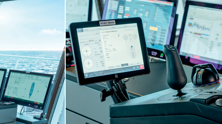
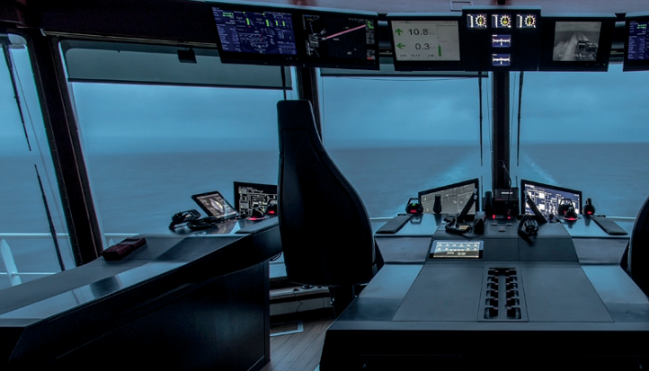
• Instruments, screens, levers and Viewcon on the bridge (1).
• Electrical cabinets in the instrument room (2) and thruster room (4).
• Instruments, screens and levers in the engine control room (3). Helicon X3 may interface several external systems (5), like Dynamic positioning systems and Autopilots.
Design
Lever
Each thruster has its own lever. Their main functions are:
• Control of pitch, RPM and azimuth direction (dependant of application)
• In operation
• Command transfer
• Lever in command
• Back-up control
• Alarm The control lever has integrated buttons and indication lamps for command transfer, backup system on/off, alarm indication/buzzer and push button for reset of buzzer. The display in the base shows set command (pitch and direction) from the lever. The lever contains two redundant electronic circuits, one for the normal control system and one for the backup system.
Control Panel
The control panel (touch screen) is the main user interface for the operator and gives an overview of all the thrusters on the vessel. It shows the status of the system, indicates thruster forces, displays alarms, and shows selected modes. The flat button on the top of the screen is for dimming the illumination of the LCD display. The screen is divided in two areas: a menu area in the left part of the screen, and a bigger command area to the right. The menu buttons to the left selects the content of the command area.
There is one command page for each thruster, in addition to one system overview page and one alarm page. The overview page shows the most essential information for all thrusters, but to activate functions or to view all available information for a thruster, the particular thrusters’ page must be selected. The graphical design is based on the following principles:
• All functions pages are only one click away
• Large and simple buttons which are easy to read.
• Same design theme for all clickable objects.
• To avoid unintentional activation of functions, all function activation buttons require press on the accept button to proceed
Emergency stop and dimmer panel (optional)
The emergency stop is used to shut down the thrusters immediately. There is one button per thruster unit. The wheel (1) is used for dimming the background light on the indicators situated on the same control station. The dimmer may be delivered in a separate panel, if the emergency stop buttons are not part of the delivery scope.
Indicators
The indicators give feedback on various data and can be found on the bridge and in the engine control room. There are three main types of indicators:
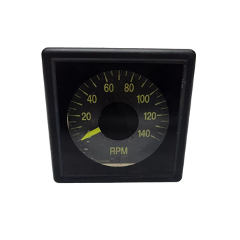
• Azimuth indicator • RPM indicator
• Pitch indicator In addition a bridge order indicator may be delivered on some vessels.
Viewcon
Network cabinet MAX PITCH ASTERN AHEAD BOW AZIMUTH THRUSTER 1 RPM MIN MAX RPM MIN MAX STBD MAIN PROPULSION PITCH ASTERN AHEAD RPM MIN MAX The network cabinet(s) contains several switches. The network cabinet(s) connects the panel PCs and the controller cabinets. Network Operator stations and electronic units are linked together in an Ethernet network. The network is single and may contain several separate switches. (CAN bus is the internal communication between levers, I/O modules and Marine Controller.)
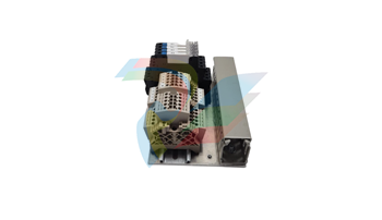
Controller cabinet
Usually located on bridge or in instrument room. This cabinet distributes signals to and from the bridge and ECR. It controls all the signals from the Helicon X3 and send them to the I/O cabinet. There is one controller cabinet per propeller/thruster. Communicates with the I/O cabinet located in the thruster room.
Rolls-Royce Marine Controller (Normal) 2. Rolls-Royce Marine Controller (Backup) 3. I/O modules 4. Power distribution 5. Network switches and terminals 6. Signal isolation amplifiers (optional) 7. Power Distribution 8. Main power supply (AC) / fuses 9. Backup power supply (DC) / fuses
I/O Cabinet
The I/O cabinet is often located in the thruster room near sensors and actuators. This cabinet distributes signals to the different propulsion/thruster units. There is one I/O unit per propeller/thruster. The I/O cabinet sends signals to the actuators on the propellers/thrusters and receives signals from the sensors. There is CAN bus communication between each I/O and controller cabinet.
Functions
Tunnel Thruster Control Functions The control functions included in the Tunnel Thruster Control system: • Pitch control • Command transfer Main Propulsion Azimuth Control Functions The control functions included in the Main Propulsion Azimuth Control system:
• RPM control
• Azimuth control
• Command transfer
Pitch Control
The function of the pitch controller is to move the propeller blades in accordance to the control lever order. The actuator unit represents the interface between the remote control and the main servo system, which performs the actual positioning of the blades.
Normal Control
The output from the pitch controller is computed on the basis of the input signals from pitch lever and the actuator position feedback. Lever and feedback signals are scaled and checked against adjustable limits, with corresponding alarm for exceeding the normal range. The levers have one set of adjustments (minimum, zero and maximum) for each manoeuvre station. Multiple sets of feedback adjustments (minimum, zero and maximum) are available for various engine power take-outs. In combined mode the lever signal is modified in a Combinator program, see chapter Pitch and RPM Combinatory (combined Control).
Backup Control The Backup Control system consists of closed loop control identical to the Normal Control system. The Backup Control is a separate system, and is independent of the Normal Control system. A system failure in the Normal Control system will automatically switch to and engage the Backup Control. Lever order signals and feedback are monitored and verified against adjustable alarm limits. If the signals exceed the limits this will release an alarm to the alarm plant and both visual and audible system failure alarm will be actuated at the manoeuvre stations. Backup Control Operation If a failure occurs on important parts of the Normal Control for the Pitch, Azimuth or RPM Control function, the control will automatically be switched over to the Backup Control system. A system failure audible and visible alarm will be activated on each of the control panels. The thruster control will continue to follow the lever in command and transfer is done by using the common in command buttons. The command can be transferred between all bridge position and the bridge control levers will continue to work as in normal control. A failure that occurs on important parts of the Backup Control for the Pitch, Azimuth or RPM Control function will not affect the Normal Control system. If a system failure occurs on the Backup Control an audible and visible alarm will be activated on each of the control panels. Backup Control Limitations The Backup Control system has only interface to the control levers. The Backup Control system does not have interface to External Control systems like Dynamic positioning systems, Joysticks or Autopilots.
Pitch Indication The Pitch Indication system is independent of the Normal Pitch Control system by means of separate transmitters and electronic circuits. The pitch indicators are connected in series and are driven from the Backup Control system. Pitch Order Scaling The system may need to reduce the pitch order for different reasons. The pitch reduction can either be activated from a digital or anlogue input signal. To reserve engine power to heavy consumers as alternators, fire pumps, etc., it may be necessary to reduce the available propeller output power. This is normally done by means of a fixed propeller pitch reduction. If the drive motor is a diesel engine the system is prepared to handle a fuel limiter contact, from the RPM governor (i.e. high scavange air pressure). If the contact is closed the pitch order will stop increasing to a higher value, only decrease of pitch order against zero is possible. For azimuth thrusters, a pitch reduction will be activated if the azimuth order is changed faster then the thruster azimuth servo can follow. Thruster Azimuth Control The azimuth control function is to obtain the correct thruster azimuth position in accordance to the control lever order. Valve controlled hydraulic motors or frequency controlled electro motors perform the positioning of the thruster azimuth. Detailed information regarding the hydraulic system or motor data is available in the Thruster Instruction manual.
Normal Control The azimuth controller computes the thruster position and order on the basis of signals from the thruster feedback and control levers. A two-wiper linear potentiometer provides two outputs with 90 degrees of phase shift named cosine and sine phase respectively. The lever order signals and feedback signals are monitored and verified against alarm limits. If the signals exceed the limits this will release an alarm to the alarm plant with a visual and audible system failure alarm on the manoeuvre stations. Backup Control The Backup Control system consists of closed loop control identical to the normal control system. The Backup Control is a separate system, and is independent of the Normal Control system. A system failure in the Normal Control system will
automatically switch to and engage the Backup Control. Lever order signals and feedback are monitored and verified against adjustable alarm limits. If the signals exceed the limits this will release an alarm to the alarm plant with a visual and audible system failure alarm on the manoeuvre stations.
Backup Control Operation If a failure occurs on important parts of the Normal control for the Pitch/Azimuth/RPM control function, the control will automatically be switched over to the backup control system. A system failure audible and visible alarm will be activated on each of the control panels. The thruster control will continue to follow the lever in command, and command transfer is done by using the common in command buttons. The command can be transferred between all bridge position and the bridge control levers will continue to work as in Normal Control. A failure that occurs on important parts of the Backup control for the Pitch/Azimuth/ RPM control function, will not affect the Normal control system. If a system failure occurs on the Backup Control an audible and visible alarm will be activated on each of the control panels
Backup Control Limitations The backup control system has only interface to the control levers. The backup control system does not have interface to external control systems like Dynpos, Joystick or Autopilot.
Local Control Local control is used if both the normal control and the backup control fail to operate the thruster azimuth. The thruster azimuth can be operated locally on the actuator unit. The Control System must first be disconnected from the actuator unit. This can be done by means of the Local Control switch mounted in front of the Actuator Interface Unit, or by disconnecting the plug from the actuator unit. If frequency converter used, operate service switch inside converter cabinet. The Thruster Instruction Manual will give more details for Local Control operation. Azimuth Indication The azimuth indication system independent of the normal control system by means of separate transmitters and electronic circuits. The Azimuth indicators are connected in series, and are driven from the Backup Control system.
RPM Control The RPM Control function system controls the speed signal to the frequency converter for electrical drives or the engine governor for diesel or gas engines. RPM Control Electric Drive Motor The RPM Control system includes selection of different operational modes:
• Separate Mode
• Combined Mode Selection between modes is possible by means of push buttons. RPM Control can be managed from engine control room only or from additional control panels. External RPM Control External RPM order signals from system as DP/Joystick/Auxiliary systems can be connected to the rpm controller. The external rpm signal are checked against adjustable preset limits. Any error conditions on the rpm input signal will initiate a warning to the alarm plant and an error message will be displayed on the control panel. RPM Order Output The output signal from the controller is scaled to meet the actuator signal range from idle to full rpm, and then fed to external governor, IP converter or frequency converter. The output will follow a linear curve between idle and full rpm order. The RPM output rate of change is adjustable and can be adapted to the engine/frequency converter reversing speed from idle to full rpm (increasing order) and vice versa (decreasing order). Propeller/Shaft RPM Indication The propeller/shaft RPM indicators are connected in series and are driven from the Backup Control system. Command Transfer The term Command transfer is used to describe the procedure performed when the control is transferred between manoeuvre stations without acceptance on either of the stations. This is normally the procedure between wheelhouse (bridge) stations.
5 Location of Manufacturing Number
5.1 Marking Locations Electrical cabinets and junction boxes are physically marked with a unique tag, and also on all applicable drawings. The I/O cabinets are marked with the Rolls-Royce logotype in the upper left corner.
Company Identification
The Rolls-Royce Company Identification sticker shows where the product has been produced and is found on discrete places on all delivered items, e.g. on the inside of the cabinet doors.