Call us 24/7+86 18150137010
Welcome to Industrial Control Trading Co., Ltd. Email: itadcs@163.com Whatsapp:+86-17750137010
Call us 24/7+86 18150137010

Woodward 8440-2052 easYgen-3200-5/P2 Genset Controller

Woodward 8440-2052: easYgen-3200-5/P2 Genset Controller

The Woodward 8440-2052 is a high-performance, versatile generator set controller belonging to the easYgen-3000 series (specifically the easYgen-3200-P2 model).

1 It is designed to manage complex power generation systems, providing comprehensive control, protection, and peer-to-peer paralleling for up to 32 generator sets.2

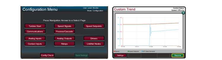
As a “Package 2” (P2) model, it includes an integrated HMI with a color display and three additional freely configurable PID controllers for advanced process automation.3

Technical Parameter Table

ParameterSpecification
ManufacturerWoodward
Part Number8440-2052 (Model: easYgen-3200-5/P2)
Power Supply12/24 VDC (Operating range: 8 to 40 VDC)
Intrinsic ConsumptionMax. 17 W
Current Inputs5A CT (Current Transformer)
Voltage Measuring100 VAC and 400 VAC (Configurable up to 650,000 VAC primary)
DisplayIntegrated Color LCD with soft keys
I/O CapacityUp to 12 Discrete Inputs / 12 Discrete Outputs (Configurable)
Analog Inputs3 Freely Scalable (0–2000 Ω, 0–1V, or 0–20 mA)
CommunicationCAN (J1939/CANopen), RS-485, RS-232, Modbus RTU
Operating Temp-20°C to +70°C

Product Advantages and Features

Integrated LogicsManager™: Built-in programmable logic allows users to create custom control sequences, often eliminating the need for an external PLC.4

Advanced Paralleling: Supports load sharing and synchronization for up to 32 units in island mode or parallel with a utility grid.5

True RMS Sensing: High-precision voltage and current monitoring (Class 1 accuracy) ensures stability even in systems with high harmonic distortion.6

FlexIn™ Technology: Analog inputs are highly flexible, supporting various resistance sensors and mA signals without extra hardware.

Multi-Lingual HMI: The operator interface supports 14 standard languages, making it ideal for global deployments.7

Robust Protection: Includes over/under voltage, frequency, and speed protection, as well as unbalanced load and phase rotation monitoring.8

Application Cases

8440-2052

The 8440-2052 is the “brain” for critical power infrastructure:

Data Centers & Hospitals: Managing emergency standby power with Automatic Mains Failure (AMF) detection and fast-start synchronization.9

Island Prime Power: Used in remote villages, oil and gas platforms, and mines to manage multiple gensets sharing a local grid.10

Cogeneration (CHP): Utilizing the three P2-specific PID controllers to manage heat recovery processes alongside electrical power production.

Microgrids: Integrating renewable energy sources with traditional diesel or gas generators for stable power distribution.11

8440-2052

Related Models & Series

The easYgen-3000 family consists of several variations based on mounting and feature sets:

Other Models in the Series

8440-2050 (easYgen-3200-5/P1): The “Package 1” version (standard features, no extra PID controllers).12

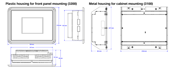
8440-2051 (easYgen-3100-5/P1): Back-panel mount version (no display/buttons on the unit).

8440-2082 (easYgen-3200XT): The newer XT series with enhanced processing and Ethernet communication.13

8446-1048 (RP-3000): Remote operator panel used to control easYgen units from a distance.14

Related Accessories

LS-5 Series: Circuit breaker controllers used for complex bus-tie management in multi-breaker systems.

ToolKit Service Tool: Woodward’s software used for configuration and real-time monitoring of the 8440-2052 via PC.15

Woodward PEAK200-HVAC 8200-1501 Digital Control for Steam Turbines

Peak200

PEAK200-HVAC  8200-1501

Digital Control for Steam Turbines

The Peak200 controller is designed to

operate small single valve, or single valve

rack industrial steam turbines. This cost

effective steam turbine controller includes

specifically designed algorithms and logic

to start, stop, control, and protect small

industrial steam turbines or turbo

expanders driving compressors, pumps, or

industrial fans.

The Peak200 control’s unique PID

structure makes it ideal for applications where it is required to control steam plant

parameters like turbine speed, turbine load, turbine inlet header pressure, turbine

exhaust header pressure, pump flow, or compressor discharge, or suction pressure.

The control’s special PID-to-PID logic allows stable control during normal turbine

operation and bumpless control mode transfers during plant upsets, minimizing

process over or undershoot conditions. The Peak200 controller senses turbine

speed via passive speed probes and controls the steam turbine through an actuator

connected to the turbine inlet steam valve(s). Peak 200 includes Woodward’s

patented adaptive PID controller that allows users automatic calculation for optimum

dynamic gains at their individual plant system.

Designed to function as a plant DCS node the Peak200 controller can be configured

to interface with the plant DCS via hardwired inputs/output signals or serial or

Ethernet communications. With the capability to monitor and control all turbine and

driven equipment based functions (i.e. bearing temperatures, vibration levels, control

oil levels, etc.) the Peak200 controller is ideal for use as a cost-effective turbine

control/protection as well as plant DCS monitoring node.

Alternatively the Peak200 can be configured to accept a remote turbine speed/load

demand from the plant DCS via a 4-20mA signal, discrete raise/lower commands, or

Ethernet or Serial Modbus communications.

PEAK200-HVAC 8200-1501

The Peak200 control also includes a special “Cascade” PID control function that can

be optionally configured and used to control any system process, related to or

affected by turbine speed or load. Typically, this controller is configured and used to

control turbine inlet header pressure, turbine exhaust header pressure, pump flow, or

compressor discharge, or suction pressure. The Cascade PID compares a 4–20 mA

process signal with an internal set point to directly position the Speed PID

controller’s setpoint, thus changing turbine speed or load until the process signal and

set point match. By cascading these two PIDs in this fashion, bumpless transfers

can be performed as well as turbine min/max.

Ethernet and serial communications allow users to easily connect the Peak200 in to

plant or process control system. All controller inputs, outputs, and statuses can be

monitored and all start/stop or enable/disable commands can be given through

industry standard Modbus TCP. The Peak200 uses SNTP (synchronized network

time protocol) over Ethernet to allow users to synchronize the Peak200’s real-time

clock to the plant distributed control system.

PEAK200-HVAC 8200-1501

The Peak200 control is available in either bulkhead models designed to be mounted on a wall or skid near the

turbine or panel-mount models designed to be installed within a standard panel or cabinet door. The product is

designed to meet NEMA 4x corrosion resistance tests and has an ingress protection rating of IP56. protecting it

against dust and water jets.

The control’s front panel serves as both a programming station and operator control panel (OCP). This user-friendly

front panel allows engineers to access and program the unit to the specific plant’s requirements, and plant operators

to easily start/stop the turbine and enable/disable any control mode.

Password security is used to protect all unit program mode settings. The controller’s 5” graphical display allows

operators to view actual and setpoint values from the same screen, simplifying turbine operation.

Turbine interface input and output wiring access is located on the controller’s lower back panel. Un-pluggable

terminal blocks allow for easy system installation, troubleshooting, and replacement. Optionally users can increase

the number of inputs and outputs signals to/from the Peak200 control by connecting LinkNet-HT distributed I/O

nodes to the controller’s CAN communication ports and configuring the Peak200 control to use the connected

distribute inputs and outputs. The following additional I/O signals can be connected to the Peak200 control via CAN

communications:

• (8) 4-20mA input channels and 2 4-20mA output channels (via 1 LinkNet-HT AIO module)

• (8) RTD signals (via 1 LinkNet-HT RTD module)

• (16) Discrete Inputs (via 1 LinkNet-HT DI module)

• (16) Relay output drivers (via 1 LinkNet-HT DO module)

Designed for steam turbine control, the Peak200 control includes two PID controllers (Speed & Cascade) multiple

startup routines (manual, automatic, remote control), and multiple protection functions (overspeed, critical speed

range, etc.) which can be configured by a user depending on the specific turbine application’s requirements. Users

can configure the Peak200’s different PID controllers, start routines, and protection levels themselves without the

need for a special control engineer. Once configured, the Peak200 performs a configuration check routine to ensure

that the programmer did not make any basic configuration mistakes.

Optionally users can utilize Woodward’s RemoteView software program with the Peak200 to function as a remote

operator control panel and or engineering station. This software program once loaded onto a remote computer or

touch panel, allows the user the following additional functionality:

• Perform the identical Peak200 front panel display functions (monitor, operate, tune, and configure) on the

respective computer or touch panel.

• Full function free for 2 hours

• Licensable for continuous GUI operation

• Password based login level security is utilized allowing function management for RemoteView applications

Refer to Woodward product specification B03424 for additional information.

The Peak200 includes a suite of service tools to allow users to perform the following functions:

• Upload configuration settings files from the Peak200 to save on another device

• Download configuration settings files to the Peak200

• View real-time or saved trend files

Control

• Dual dynamics (Speed PID)

• Adaptive speed/load PID dynamics

• Cascade PID (turbine/driven equipment pressures or

flows)

• Manual or auto start sequence

• First-Out indication (alarms & shutdowns)

• Peak speed Indication for overspeed trip

• Multi-lingual Display (English & Additional

Languages TBD)

• Remote analog setpoints for Speed/Load & Cascade

• Bearing temperature monitoring/alarms/trips

• Vibration monitoring/alarms/trips

System Protection

• Overspeed protection logic & test capability

• Critical speed band protection (1 band)

• First-out Indication (5 individual shutdown inputs)

• Bearing temperature alarm and trip settings

• Turbine vibration alarm and trip settings

• Control CPU & memory failure detection logic

• Mode login level password security

Cost-Effective Design— The Peak200 control is

designed to function as the turbine control, system

sequencer, operator control panel, and first-out indicator.

This encompassing design minimizes external system

devices as well as system installation, wiring, and

troubleshooting. This field configurable controller allows

major functional changes to be made at site, often by

knowledgeable plant personnel, and minor functional

changes to be online as process changes require. The

Peak200 control’s first-out-indicator logic indicates

internal as well as external system related alarm and

shutdown conditions, greatly simplifying and reducing

system troubleshooting.

Communications— The Peak200 controls can

communicate directly with plant Distributed Control

Systems and/or operator control panels, through two

Ethernet ports using Modbus TCP or UDP

communication protocols or via a serial Modbus port.

The Peak200’s serial port supports RS-232 or RS-485

communications using ASCII or RTU Modbus protocols.

Communications between the Peak200 and a plant DCS

can also be performed through hardwired connections.

Woodward 8237-1369 Speed protection

8237-1369

The 8237-1369 provides various pre-defined test routines including an automated periodic test routine to assist users with verifying system operation.

8237-1369 Technical Specifications

Dimensions    330 x 445 x 159 mm

Electromagnetic Compatibility    Emissions: EN61000-6-4 Immunity: EN61000-6-2

Enclosure Type    IP56 when installed correctly

Features    Reverse Polarity Protection for DC

High Input Voltage    Nominal 115 Vac / 240 Vac / 125 Vdc

Keypad/Display    15 Keys per module

Low Input Voltage    Nominal 24 Vdc

Operating Temperature    –20 to +60 °C (–4 to +140 °F)

Relative Humidity    Up to 95% (non-condensing)

Storage Temperature    –20 to +65 °C (–4 to +158 °F)

Weight    23 lbs before shipping

About the 8237-1369

8237-1369

Model 8237-1369 is an over speed detection device that can be configured to work with various turbines.

It is part of the ProTech-GII series from Woodward and fits any size of hydro, steam, or gas turbine.

In the event of over acceleration, this product will safely shut down the system.

Speed readouts for this device are between 4 and 20 mA, and it uses Modbus communication relays.

In addition to acceleration detection, model 8237-1369 also uses MPU detection.

This product performs routine tests to make sure each module is functioning properly.

A conformal coating material makes this speed safety device resistant to sulfur contamination, as well as H2S and SO2 gases.

8237-1369

Woodward ESDR 4 Current Differential Protection Relay

ESDR 4

Current Differential Protection Relay

The ESDR 4 is a three-phase current differential protection relay for generators and motors (protected object).

The currents flowing in the individual lines are each measured using a current transformer on both sides of the

protected object. They form the protection area boundary or zone. All two or three-phase short circuits and line

to-earth faults within this protection area are detected by the ESDR 4 as fault currents which initiate tripping.The

unit does not trip if fault currents occur outside the protection zone. In this way, a selective protection is guaran

teed.

The unit monitors six (6) measured currents via isolated inputs. The unit calculates internally the restraint current

(Is) and the differential current (Id) separately for each phase. The actual values of the calculated parameters (Dif

ferential current Id und Restraint current IS) are shown on the display either as absolute values or as a percentage

of the generator rated current (selectable in locked input mode).

ESDR 4

Theoretically the currents Ia and Ib are equal, both in fault-free operation and outside the protection zone (Figure

4-1-a).The difference is zero and the differential protection does not initiate. However, in practice current differ

entials do occur (= spurious currents), even in fault-free operation. They result, for example, from summation or

phase angle errors in the CTs, which are influenced by deviating burden values. These spurious currents remain

small inside the operating range, but increase with increasing load and are especially high when one or more CTs

become saturated (e.g. in the case of an external short circuit). In order to prevent a tripping of the relay due to

spurious currents, the trigger threshold is not held statically constant but increases in relation to the restraint cur

rent Is.  Spurious currents need to be taken into account when adjusting the trip characteristic.

When a fault occurs inside the protection area (Figure 4-1-b), unequal currents flow in the CTs, which result in a

current differential. If this exceeds the differential protection threshold, the relay will trip.

Monitoring of the Differential Current

ESDR 4

The monitoring of the differential current is carried out in two stages..

The first monitoring level serves as a warning and can be enabled or disabled. Should the adjustable warning

characteristic be exceeded, a text appears in the display and a relay contact is enabled. The pick-up time and the

dropout delay of the relay output are adjustable. The warning stage of the monitoring is auto-resetting.

The second stage of monitoring (main stage) serves to initiate tripping. In contrast to the first stage, it offers the

possibility to monitor the overstepping of an adjustable tripping characteristic (Id < In) and additionally, a fixed

tripping-threshold of 100%, relative to the generator rated current (Id > In). The trigger-delay for each limit value

may be independently adjusted, thus allowing a shorter triggering time at higher differential currents. When one

or both tripping characteristics are exceeded, a text display is initiated and two relay contacts are energized. The

tripping characteristics possess a 2% hysterisis relative to the generator rated current. .

The signal relay is only automatically reset if the function “automatic reset relay” in the Entry field on the screen

is configured to “on”. Otherwise, the resetting is carried out by pressing the “Clear” button on the front of the

unit or via the discrete input terminal 18 “reset”.

The two monitoring levels can also be used to change the characteristics of the control function (stage 1: small

value and a long time; stage 2: high value and a short time)

Tripping Characteristic

The following figure shows the tripping and warning characteristics (with sample values for X12. Y1.and Y2). It

represents the tripping and warning thresholds (Y) relative to the restraint current (X) The positions of the corner

points are determined by the coordinates P (X12/Y2) and P (X12/Y1). The selection of these positions is depend

ent on the generator being protected. The following gives the ranges of tripping and warning thresholds:

IS / IN

IS / IN

IS / IN

0 to X12

X12 to 5 × IN

> 5 × IN

The threshold Id is independent of the restraint current..

The threshold Id is dependent on the restraint current. A change of 100% in the

restraint current causes an increase of 10% in the tripping threshold.

The threshold Id stays constant at 85%.

Different characteristics can be chosen for the first and second monitoring levels, whereby the horizontal position

(X-coordinate) is valid for both stages. The vertical position (Y-coordinate) can be chosen separately for each

monitoring level. This results in a fixed difference in thresholds of the first and second monitioring levels for

each restraint current Is.

Control Inputs

Configuration

Terminal 17

Acknowledgement

Terminal 18

Blocking

Terminal19

Relays

Tripping (relay 1)

Terminals 1/2/3

Tripping (relay 2)

Terminals 4/5/6

Warning (relay 4)

Terminals 11/12/13

Ready for operation

(relay 3)

Terminals 7/8

When this input is energized, the unit locks into Configuration mode and stays in this

mode until the terminal is de-energized.

If this input remains energized for at least 1 s, the faults detected in monitoring

level 2 are reset. This means that the relays will be de-energized and the text display

will be deleted from the screen as long as the monitored currents are not exceeding

the configured threshold level.

When this input is energized, the differential protection is disabled.This means that

the differential current is not monitored, no relay can be enabled and no text is dis

played.

This relay becomes enabled when the unit detects threshold limit 2 (main stage) has

been exceeded. The configured differential current characteristics and delay time will

determine how relay 1 functions.

This relay becomes enabled when the unit detects threshold limit 2 (main stage) has

been exceeded. The configured differential current characteristics and delay time will

determine how relay 2 functions.

This relay becomes enabled when the unit detects threshold limit 1 has been ex

ceeded. The configured differential current characteristics and delay time will deter

mine how relay 4 functions.

This relay is enabled when the unit is operational and the differential current is being

monitored. The relay becomes disabled if the monitoring is deactivated through any

of the following reasons:

• the internal self-monitoring has detected a malfunction of the unit. A correct func

tioning of the unit cannot be guaranteed and corrective action may be necessary.

• the set values for parameter “CT-ratio” or parameter “Generator Current” are out

side the permissible limits (see page 19).

• the digital input “Blocking” is energized.

• the parameter “Monitoring” is configured to “Off”.

When in configuration mode (simultaneous pressing of “Digit↑” and “Cursor→”), the configuration screen can

be advanced by pressing the “Select” button. Should there be no entry, parameter change or other action for 60

seconds, the unit will automatically revert into Automatic mode.

During the configuration mode, the monitoring function is still active. This means inevitably, that while adjusting

parameters during operation, it is possible to cause a tripping of the relay.

adjust settings

[press “SELECT”]

Configuration mode “Select” button

Pressing the “Select” key activates the configuration mode, and the following pa

rameters can be enabled or changed within the given limits. Please you note that as

you advance through the configuration screens, by configuring some parameters as

“ON”, additional screens must be configured relating to that parameter. If the pa

rameter is configured as “OFF”, the additional screens will be disabled and not dis

played.

Software version

Software version

Displays the software version.

SPRACHE/LANGUAGE —————-

Language selection english/german

The screens can be displayed in German or English.

curr. transform.

ratio     0000/x

CT-Ratio Selection 10 to 6.000/{x} A

The Ratio of the CTs being used is entered here. The CTs should be selected so that

in fault-free operation at generator rated current, at least 60 % of nominal current

flows in the CT-secondary. Failure to use properly a sized CT-Ratio leads to loss of

resolution and inaccuracies in the monitoring functions.

generator nomin.

current    0000A

Generator rated current 5 to 6.000 A

This value is used as reference value for the calculation and display of restraint cur

rent and differential current. The entered value of generator current must be at least

60% of the nominal current of the CT and must not exceed the entered value of  CT

nominal current.

Example CT-Ratio 500/5 A

Range of Generator rated current 300 A to 500 A.

If the nominal value is less than 50% of the transformer ratio, the message “Wrong

Entry” will be displayed on the screen in Automatic mode and the unit will de

activate monitoring functions (the Monitoring LED goes out).

automatic reset

relay       ON

Automatic reset of the relay ON/OFF

Applies only to monitoring level 2 (tripping).

Monitoring level 1 (warning) always Auto-resets.

ON…………….The relays de-energize automatically when the fault is no longer pre

sent. The screen input “Automatic reset of error text” determines

what happens to the Alarm-text in the display.

OFF…………..The relays remain energized until they are reset.

monitoring

ON

Monitoring ON/OFF

ON…………….Monitoring of the differential current is active and the follow

ingscreens of this option are displayed.

OFF…………..The monitoring is de-activated and the following screens are not dis

played.

release limit

Is/In     X=000%

Trigger Value IS/IN (X12) 50 to 300 %

Definition of the threshold characteristic for the monitoring of levels 1 and 2.

This value determines the horizontal position (X12-coordinates of points

P [X12/Y1] and P [X2/Y2]) of the corner points of the Warning and Tripping char

acteristics.

release limit

Id/In     Y=000%

Limit valueId

This value determines the vertical position (Y2-coordinate) of the corner point

P [X12/Y2] of the tripping characteristic (monitoring level2).

pick-up t. Id>IN

release    0.00s

Relay enable delay time for Id>IN (monitoring level 2) 0.04 to 3.00 s

If the differential current surpasses the generator rated current without interruption

over this time period, a fault condition for exceeding the threshold limit will be ini

tiated.

pick-up t. Id<in< p=””></in<>

release    0.00s

Relay enable delay time for Id

If the differential current surpasses the adjusted trigger threshold without interrup

tion over this tme period, a fault condition for exceeding the threshold limit will be

initiated.

release time

release    0.00s

Relay disable delay time (monitoring level 2) 0.10 to 3.00 s

Only visible when the screen “Automatic reset of the relay” is configured to

ON .

If the differential current value which initiated the fault condition should fall 2% or

more below the trigger threshold limit and remain uninterrupted for the period of

time configured here, the fault condition will be terminated and the relay output

and the fault text will be reset.

automatic reset

error text   ON

Automatic reset of error text ON/OFF

Only visible when the screen “Automatic reset of the relay” is configured to

ON

ON…………….The displayed fault text will be automatically deleted, when the fault

conditions are no longer detected.

OFF…………..The displayed fault text must be deleted manually, and can only be

done when fault conditions are no longer detected.

automatic reset

error text   00s

Delay for automatic reset of error text 1 to 60 s

Only visible when the screens “Automatic reset of the relay” and “Automatic

reset of error text” are configured to ON

The fault text will automatically delete, when the fault conditions are no longer de

tected for the time period set here.

warning

ON

Warning (monitoring level 1) ON/OFF

ON…………….The adjustable warning characteristic is being monitored and the fol

lowing screens of this option are displayed.

OFF…………..The adjustable warning characteristic is not being monitored and the

following screens of this option are not displayed.

warning limit

Id/IN    Y=00.0%

Trigger value Id/IN (monitoring level1. Y1) 3.0 to 40.0 %

Only visible when the screen “Warning” is configured to ON.

This value determines the vertical position of the corner point of the warning char

acteristic. The horizontal position (X12) is identical with that of the trip character

istic. Usually the warning limit is lower than the trip limit value.

pick-up time

warning    0.00s

Enable delay time of the “warning” relay (monitoring level1) 0.04 to 3.00 s

Only visible when the screen “Warning” is configured to ON.

If the differential current exceeds the warning threshold curve without interruption

over this time period, the control recognizes that the warning limit has been ex

ceeded.

release time

warning    0.00s

Relay disable delay time (monitoring level 1) 0.10 to 3.00 s

Only visible when the screen “Warning” is configured to ON

If the differential current value which initiated the warning should fall 2% or more

below the trigger threshold limit and remain uninterrupted for the period of time

configured here, the fault condition will be terminated and the relay output and

fault text will be reset.

display value

Id           [-]

Display – measured value Id in [%] / [A]

[%]……………The percentage of the rated generator current that is measured is dis

played on the screen.

[A]:……………The measured absolute values are displayed on the screen.

display value

IS           [-]

Display – measured value IS in [%] / [A]

[%]……………The percentage of the rated generator current that is measured is dis

played on the screen.

[A]:……………The absolute measured values are displayed on the screen

Woodward easYgen-3000 Genset Control for

easYgen-3000

Genset Control for

Multiple Unit Operation

The easYgen-3000 is a control unit for genset management applications. The numerous inputs and outputs,

along with a modular software structure, permit you to use the easYgen-3000 for a wide range of applications

with only a single part number. This includes stand-by, AMF, peak shaving, import-export, cogeneration or

distributed generation, among others. Also the easYgen-3000 is compatible for island, island parallel, mains

parallel and multiple unit mains parallel operations.

The easYgen-3000 is able to control up to 32 gensets connected in a network with automatic sequencing.

The easYgen-3000 is available in two variants, the easYgen-3100 for cabinet back panel installation, and the

easYgen-3200 with graphical display and soft keys for front panel mounting.

FlexAppTM – This feature provides the tools to easily configure the number of operated breakers: None, GCB,

GCB and MCB.

LogicsManagerTM – Woodward’s LogicsManager software enables to change the operation sequences and

adapt them to specific needs. The LogicsManager accomplishes this by monitoring a range of measuring val

ues and internal states, which are combined logically with Boolean operators and programmable timers. This

enables to create and/or modify control and relay functions.

easYgen-3000

FlexInTM – The analog inputs are configurable to operate with VDO, resistive, and/or 0 to 20 mA senders.

Flexible Outputs – Speed and voltage bias outputs are configurable to function with all speed governors and

voltage regulators. The outputs can also be used as freely scalable outputs (e.g. for driving external meters).

FlexCANTM – Advanced network interfaces ensure unsurpassed control performance – from engine control up

to total plant operation. The easYgen-3000 is capable of working with all common industrial interfaces, includ

ing CAN, RS-232. and RS-485. The multiple communication protocols permit the easYgen-3000 to communi

cate with a vast majority of engine control units (ECUs), external I/O boards, PLCs, and modems. CANopen,

J1939. Modbus RTU, and Modem protocols are supported.

DynamicsLCDTM – The adaptive and interactive 5.7″, 320×240 pixel graphical LC display with soft keys and a

clear menu structure ensures intuitive user operation and navigation.

Features

easYgen-3000

• Operation modes: Auto, Stop, Manual, and Load/No Load test modes via discrete input possible

• Breaker control: Slip frequency / phase matching synchronization, open-close control, breaker monitoring

• Load transfer features: open / closed transition, interchange, soft loading / soft unloading, mains parallel

• Process and load-dependent start/stop logic for diesel and gas engines programmable for spinning or system

reserve with fixed or dynamic priorities.

• Real and reactive power load sharing with up to 32 units

• Remote control via interface and discrete/analog inputs for adjusting speed, frequency, voltage, power, reactive

power, and power factor set points

• Complete integrated engine and generator protection as well as mains monitoring features

• Freely configurable PID controllers for various control purposes, such as heating circuit control (CHP applica

tions), water level, fuel level, or pressure and/or other process values

• Special Scania S6. MTU ADEC, Volvo EMS2 & EDC4. Deutz EMR2. MAN MFR/EDC7. SISU EEM and Wood

ward EGS02 ECU support (depending on Package)

• Counters for operating hours / engine starts / maintenance / active energy / reactive energy

• Configurable trip levels / delay timers / alarm classes for monitoring and protective functions

• Clear text display and evaluation of up to 100 J1939 analog values

• Discrete and analog I/O expansion board connectivity (Woodward IKD 1 or Phoenix Contact IL series)

• Front panel and PC configurable (ToolKit software)

• Multi-level password protection for access via HMI or interface

• Multi-lingual capability (English, German, French, Spanish, Chinese, Japanese, Italian, Portuguese, Turkish, Russian)

• Peak shaving operation

• Stand-by operation

• AMF operation

• Cogeneration (CHP)

• Isolated & mains parallel

operation

• Import/export control

• Soft loading features

• Open/closed transition

• Load sharing and load

dependent start/stop for

up to 32 units

• Programmable operation

sequences

• Multi-lingual capability

• CANopen / J1939 ECU

Control

• Modbus RTU Protocol

• CE marked

• UL/cUL Listing

• LR & ABS Marine Ap

provals

• Event recorder (300 events, FIFO) with real time clock

Power supply …………………………………………………. 12/24 Vdc (8 to 40 Vdc)

Intrinsic consumption ………………………………………………………… max. 17 W

Ambient temperature (operation) ………………….. -20 to 70 °C / -4 to 158 °F

Ambient temperature (storage) …………………… -30 to 80 °C / -22 to 176 °F

Ambient humidity ……………………………………………… 95 %, non-condensing

Voltage ………………………………………………………………………………….. ( /Δ)

100 Vac [1] Rated (Vrated) …………………………………….. 69/120 Vac

Max. value (Vmax) ……………………………………. 86/150 Vac

Rated surge volt.(Vsurge) ……………………………………………. 2.5 kV

and 400 Vac [4] Rated (Vrated) …………………………………… 277/480 Vac

Max. value (Vmax) ………………………………….. 346/600 Vac

Rated surge volt.(Vsurge) ……………………………………………. 4.0 kV

Accuracy ……………………………………………………………………………… Class 1

Measurable alternator windings ………………… 3p-3w, 3p-4w, 1p-2w, 1p-3w

Setting range ………………… primary ……………………………50 to 650.000 Vac

Linear measuring range …………………………………………………….. 1.25×Vrated

Measuring frequency…………………………………………50/60 Hz (40 to 85 Hz)

High Impedance Input; Resistance per path ……. [1] 0.498 MΩ, [4] 2.0 MΩ

Max. power consumption per path ………………………………………… < 0.15 W

Current (Isolated) Rated (Irated) ………………………… [1] ../1 A or [5] ../5 A

Linear measuring range ………………………………………………. Igen = 3.0×Irated

Imains/ground = 1.5×Irated

Setting range ……………………………………………………………….. 1 to 32.000 A

Burden ……………………………………………………………………………… < 0.15 VA

Rated short-time current (1 s) ………………………….. [1] 50×Irated, [5] 10×Irated

Power ……………………………………………………………………………………………

Setting range …………………………………………………. 0.5 to 99.999.9 kW/kvar

Discrete inputs …………………………………………………………………… isolated

Input range ……………………………………………………. 12/24 Vdc (8 to 40 Vdc)

Input resistance …………………………………………………….. approx. 20 kOhms

Measuring

Generator voltage (3-phase/4-wire)

Generator current (3x true r.m.s.)

Mains voltage (3-phase/4-wire)

Mains or ground current (1x true r.m.s.) #1

Busbar voltage (1-phase/2-wire)

Control

Breaker control logic (open and closed transition) FlexAppTM 2   2   2   2

Automatic, Manual, Stop, and test operating modes

Single and multiple-unit operation

Mains parallel multiple-unit operation (up to 32 units)  #2

AMF (auto mains failure) and stand-by operation

Critical mode operation

GCB and MCB synchronization (slipping / phase matching)

Interchange (import / export control)

Load-dependent start/stop

n/f, V, P, Q, and PF remote control via analog input or interface

Load/var sharing for up to 32 gensets

Freely configurable PID controllers –   3   –   3

HMI

Soft keys (advanced LC display) DynamicsLCDTM –   –

Start/stop logic for diesel / gas engines

Counters for operating hours / starts / maintenance / active/reactive energy

Configuration via PC #3

Event recorder entries with real time clock (battery backup) 300   300   300   300

Protection ANSI#

Generator: voltage / frequency 59 / 27 / 81O / 81U

Generator: overload, reverse/reduced power 32 / 32R / 32F

Generator: unbalanced load 46

Generator: instantaneous overcurrent 50

Generator: time-overcurrent (IEC 255 compliant) 51

Generator: ground fault #4

50G

Generator: power factor 55

Generator: rotation field

Engine: overspeed / underspeed 12 / 14

Engine: speed / frequency mismatch

Engine: D+ auxiliary excitation failure

Mains: voltage / frequency 59 / 27 / 81O / 81U

Mains: phase shift / rotation field 78 /

I/Os

Speed input (magnetic / switching; Pickup)

Discrete alarm inputs (configurable) 10   10   10   10

Discrete outputs (configurable) LogicsManagerTM max. 12   max. 12   max. 12   max. 12

External discrete inputs / outputs via CANopen (maximum) 16 / 16   32 / 32   16 / 16   32 / 32

Analog inputs #5 (configurable)  FlexInTM 3   3   3   3

Analog outputs (+/- 10V, +/- 20mA, PWM; configurable)  2   2   2   2

External analog inputs / outputs via CANopen (maximum) –   16 / 4   –   16 / 4

Display of J1939 analog values (number of SPNs) 16   –   16   –

Display and evaluation of J1939 analog values (supported SPNs) –   100   –   100

CAN bus communication interfaces #6 FlexCANTM 2   2   2   2

RS-232/485 Modbus RTU Slave interface(s) 1 / 1   1 / 1   1 / 1   1 / 1

Listings/Approvals

UL Listing

cUL Listing

LR & ABS Marine Approval

CE Marked

Part Numbers

1A CT inputs / front panel mounting with display  #7 P/N 8440- –   –   1816   1842

5A CT inputs / front panel mounting with display  #7 P/N 8440- –   –   1831   1843

1A CT inputs / cabinet back mounting w/o display P/N 8440- 1818   1844   –   –

5A CT inputs / cabinet back mounting w/o display P/N 8440- 1817   1845   –   –

Spare connector kit P/N 8923- 1314   1314   1314   1314

Woodward CPC-II Current-to-Pressure Converter

CPC-II

Current-to-Pressure Converter

Applications

The CPC-II (current to pressure

converter, generation II) is an

electrohydraulic pressure-regulating

valve control designed for use in

positioning single-acting steam turbine

valve servos. This CPC’s superb

accuracy and resolution make it ideal

for steam turbine valve control and

related turbine speed and load

control. The CPC accepts a 4–20 mA

pressure demand signal and

accurately controls oil pressure to

precisely position single-acting steam

turbine governor-valves. Precise and

stable steam valve control directly

relates to improved steam turbine

speed and load control and reduced

system mechanical wear.

The CPC’s redundancy features make it ideal for critical steam turbine applications,

where turbine up-time and availability are essential. This converter can be configured to

accept redundant pressure demand inputs, from one or two (redundant) controllers, and

vote the input to follow. Alternatively the CPC can be configured to accept signals from

both its internal oil pressure sensor and an external (redundant) oil pressure sensor, and

use the voted healthy signal.

The CPC’s robust design (strong actuator, corrosion-resistant material, single moving

rotary valve, and self-cleaning port design) makes it ideal for challenging applications

where dirty or contaminated oil may be present.

• Oil contamination

resistant

• Precise fluid

pressure control

• Stable & linear valve

control

• Included valve

linearization table

• Redundant

inputs/sensors for

critical applications

• Accepts signals

from redundant

controllers

• Redundant (dual)

CPCs

(Master/Slave)

functionality

• Standard mounting

and hydraulic

connections

• Self cleaning valve

algorithm

• Status & health

indication

CPC-II

Optionally two controllers can be connected to a single CPC in a redundant Master/Slave

fashion to allow the turbine to continue to operate if either turbine control fails, or on-line

changes are desired. Designed for use in applications requiring full redundancy,

optionally two CPCs can be applied in a dual-redundant fashion, simplifying the entire

system and control wiring.

Description

The CPC is an electrohydraulic pressure-regulating valve control that utilizes a very

accurate internal pressure sensor and PID controller to precisely control steam turbine

valves. The CPC consists of a valve-actuator assembly, pressure sensor, and electronic

driver module. The unit’s driver module accepts one (or two) 4–20 mA pressure setpoints

and compares these setpoints to the sensed oil pressure, to accurately control turbine

valve oil pressure.

The CPC controls oil pressure by porting supply-oil to its control-oil output port (turbine

valve control oil) or back to the system supply tank. This converter’s special PID

architecture allows it to perform very stable pressure control during normal conditions,

and respond in milliseconds to desired valve step changes during system or plant

transients. As a means of protecting the turbine, an internal valve-return-spring forces the

CPC to a failsafe position (port oil to drain) and safely close turbine control valves upon

any internal unit failure (electrical input power failure, pressure sensor failure, processor

failure, etc.).

CPC-II

The CPC is factory and/or field configurable via a computer

based service tool. The CPC’s PCI Service Tool uses a simple

user-friendly format to allow users to easily configure,

calibrate, and adjust all internal functions and PID control

settings. The CPC includes a 4–20 mA output channel to

indicate control oil pressure level, and unit alarm and shutdown

relay outputs for use as unit health and status indications into

the system controller or plant DCS.

A Manual Stroke function allows users to manually stroke the

CPC output pressure (turbine valve position) locally at the

unit, via an internal Manual Stroke Screw. This local manual

stroke function is designed with built in security logic to

protect the users from un-intentional use of this function

during normal operation. Manual Stroke capability is also

available via remotely or locally via the CPC’s computer

based PCI Tool.

Since flow through single and staged inlet steam valves tend

to be non-linear throughout their flow range, turbine controls

are typically de-tuned to compensate for instability or

sluggish control points throughout this range. As a way of

allowing turbine control optimization, the CPC includes an

eleven-point linearization table to allow turbine OEMs or

users to compensate for poor valve linearization by digitally

linearizing the control to valve flow relationship.

Because many turbine users utilize redundant pressure

converters to increase system reliability, and because these

type of applications are prone to silting build-up problems in

the slave unit, a special “Silt Buster” (patent pending) routine

is also configurable to routinely remove internal silt build-up.

Accessories

A standard steel adapter plate is available to allow the CPC

to easily interface with systems designed for Voith I/H

converters.

Specifications

Performance

Accuracy: < ±0.2 % of full range

Repeatability: 0.1 % of full range

Temperature Drift: < ±0.01 % of full range /°C

Pressure stability: < ±2 % of setpoint

Failsafe Operation: Internal return spring forces Control Port

oil to drain port on loss of power or detected failures

Configuration: Computer based Service Tool (RS-232

communications port)

Physical

Dimensions: See outline drawings

Height x Width x Depth: Approx. (290 x 270 x 270) mm

Weight: Approximately 25 kg (55 lb) without oil

Fluid Ports: See outline drawings

Mounting: Any attitude, Four M10 threaded holes,

23 mm deep, on the face with the hydraulic ports.

Adequate support must be provided for the unit.

Environmental

Operating Temperature Range: (–40 to +85) °C

Hydraulic Supply Temperature: (15 to 70) °C

Immunity: EN61000-6-2 (2005)

Emissions: EN61000-6-4 (2007)

Shock: US MIL-STD-810C method 516.2. procedure 1 (10 G

Peak, 11 ms duration, saw tooth waveform)

Vibration: US MIL-STD 810F, M514.5A, Cat. 4 (0.015 G²/Hz,

(10 to 500) Hz, 1.04 Grms)

Ingress Protection: IP66 per EN 60529

Electrical

CPC-II

Input Supply: (18 to 32) V (dc) @ 1.5 A steady state, 8 A

peak (100 ms)

Analog Input Signals: Isolated (4 to 20) mA (250 Ω input

impedance)

Analog Output Signal: (4 to 20) mA; maximum external load:

300 Ω, Accuracy = ±1 % of full scale

Discrete Inputs: Optically Isolated (requires 24 V (dc) wetting

voltage)

Discrete Output Rating: 1 A @ 30 V (dc)

Service Tool Port: RS-232 communications via straight

through serial cable

Hydraulic

Fluid Types: Mineral or synthetic based oils may be used.

Contact Woodward for specific oil recommendations.

Maximum Input Supply Pressure: 25 bar / 363 psi

CPC-II Model

Maximum Output

Pressure Range*

Location

Rating

9907-1197

(0 to 25) bar /

(0 to 363) psi

Zone 1 & 2

9907-1198

(0 to 25) bar /

(0 to 363) psi

Zone 2

9907-1199

(0 to 10) bar /

(0 to 145) psi

Zone 1 & 2

9907-1200

(0 to 10) bar /

(0 to 145) psi

Zone 2

9907-1228

(0 to 10) bar /

(0 to 145) psi

Zone 2

9907-1349

Zone 1 & 2

(0 to 10) bar /

(0 to 145) psi

* Note: The recommended maximum output pressure is less than

70 % of the supply for the best dynamic performance.

Recommended Filtration: (24 to 40) μm nominal, β75 or ISO

20/16 Class

Recommended Viscosity 20 to 100 cSt

Specific Gravity: 0.6 to 1.0

Flow Capacity: Depends on viscosity and pressure difference

(see Figure 3)

Return/Drain Pressure: Maximum 2 bar (29 psi)

Regulatory Compliance

(Listings are limited only to those units bearing the

appropriate Marking or Agency Identification)

European Compliance for CE Marking:

EMC Directive: 2014/30/EU

ATEX Directive: 2014/34/EU For Zone 1: SIRA

11ATEX1310X II 2 G, Ex db IIB T4 Gb. For Zone 2: II 3 G Ex

nA IIC T4 Gc

Other European Compliance: (Compliance with the

following European Directives or standards does not qualify

this product for application of the CE Marking)

Machinery Directive: Compliant as a partly completed

machinery per 2006/42/EC

Pressure Equipment Directive: Compliant as “SEP” per

Article 4.3 to 2014/68/EU

Other International Compliance:

EAC Customs Union: Certified to Technical Regulation CU

012/2011 for use in potentially explosive atmospheres as Ex

d IIB T4 Gb X or 2Ex nA IIC T4 Gc X.

EAC Customs Union: Declared to Technical Regulation CU

020/2011 On Electromagnetic Compatibility of Technical

Equipment.

IECEx: Certified for use in explosive atmospheres per IECEx

Certificate IECEx CSA 11.0017X Zone 1: Ex d IIB T4 Gb and

Zone 2: Ex nA IIC T4 Gc

North American Compliance:

CSA: CSA Certified for Class I, Div. 1. Groups C and D and

Class I, Div. 2. Groups A, B, C, and D, T4 at 85°C Ambient.

For use in Canada and the United States

8290-189-EPG-installation-manual 8290-044

8290-189-EPG-installation-manual 8290-044

Installation and Operation Manual

This manual covers Electrically Power Governor (EPG) models 512/524 and

1712/1724. Refer to the appropriate manual or contact Woodward for information

about other versions of the EPG.

Application

The EPG is used to control the speed of diesel, gas, and gasoline engines. It can

also control the speed of gas turbines. Installation of EPG actuators is simple

because they require neither mechanical drive nor hydraulic supply.

The EPG handles prime movers with mechanical loads and generator loads

equally well. Generator sets which will be paralleled, however, require additional

appropriate switch gear, current and potential transformers, and the Woodward

Generator Load Sensor.

An EPG is a three-component system, requiring a magnetic pickup, speed

control, and actuator.

A battery charger must be used to keep the battery charged. Maximum steady

state current consumption is 4 A for the 12-volt models (512/1712), and 3 A for

the 24-volt models (524/1724).

Part Number Selection

Use EPG Model 512/1712 for operation in 12-volt systems. Use Model 524/1724

for operation in 24-volt systems.

Additionally, speed controls are available for four ranges of magnetic pickup

frequencies, for diesel engines and gas turbines, or for gasoline and gas

engines. Actuators have a double-ended output shaft for either clockwise or

counterclockwise rotation to increase fuel.

Speed controls and actuators must be compatible. Use the Part Number

Selection Table below (Table 1-1) to choose compatible EPG speed controls and

actuators.

8290-189-EPG

The optional Start Fuel Limit feature allows setting a maximum actuator position

during start-up. The maximum position remains in effect until the engine reaches

the selected idle or rated speed. The limit may be adjusted out of the way by

turning the adjustment potentiometer fully clockwise.

The Dual Dynamics feature allows tailoring a special set of responses for

unloaded and loaded operating conditions. This type of control is often needed

for gas engines and other systems with non-linear fuel systems. A switch is used

to change between slow and fast dynamics.

Accessories

This manual includes some information about accessories frequently used with

EPGs.

To Parallel Generators

Add the Generator Load Sensor to the EPG in paralleled generator applications.

Woodward makes many accessories for paralleled generator applications.

To Decrease Acceleration and Deceleration

The Ramp Generator or an optional, external capacitor can be used to increase

the time to go from idle to rated speeds and vice versa. The Ramp Generator

provides a linear ramp with times adjustable to 25 seconds in a typical case. It is

useful in smoke-limiting applications. Use the 8271-909 with 24 V batteries and

the 8271-910 for 12 V batteries. The capacitor provides an exponential ramp with

times up to four seconds. Exponential means it changes (speed in this case)

rapidly at first but slows as it approaches its final value. See the typical wiring

diagram for capacitor requirements.

References

These publications can be obtained from your Woodward authorized Distributor

or AISF (Authorized Independent Service Facility). All are also available on the

Woodward website (www.woodward.com).

Catalog

52122

Product

Specification

04106

Manual

25070

82510

Title

Woodward Industrial Control Product Line Catalog

Title

Model 512/1712 & 524/1724 Electrically Powered Governors

Title

Electric Governor Installation Guide

Magnetic Pickups for Electric Governors

direction of rotation for increased fuel by choosing a suitable linkage.

If you are using a Woodward supplied installation kit, follow its instructions and

skip over Linkage Compatibility. Begin again with Installing the Magnetic Pickup.

Linkage Compatibility

Also match linkage linearity to the fuel control. Use a linear linkage as shown in

Figure 2-2 unless the prime mover has a carburetor or other non-linear fuel

control. See Figures 2-3 and 2-4 for a carburetor compensating linkage. Contact

Woodward if a linkage different from those shown is required. Incorrect linearity

matching can cause stable operation at some fuel settings but oscillation at other

fuel settings.

A return spring is included in the actuator. Do not use an additional return spring.

(Low force return springs that may be located in an engine’s valve cover usually

don’t affect EPG performance.)

Make sure that the actuator is capable of moving the fuel control to the maximum

and minimum limits. Let the fuel control limit actuator travel. Set the linkage so

that the actuator is just above minimum when the fuel control is at its minimum

stop and (except for Detroit Diesel engines) so that the actuator is just below

maximum when the fuel control is at its maximum stop. We recommend that

Woodward installation kits be used for Detroit Diesel engines.

Use good rod end connectors. The link connecting the actuator lever to the fuel

control lever must not be so long that it flexes when the prime mover is running.

Installing the Magnetic Pickup

Mount the magnetic pickup through a housing or rigid bracket. Make sure that

the sensed gear is of magnetic material. The gap between the pickup and the

outside diameter of the gear should be set to approximately 1.0 mm (0.04”) at the

closest point (radial runout). Using the pickup with small gears may require

spacing as close as 0.25 mm (0.010”).

If you cannot measure the gap directly, it can be set in this manner: with the

prime mover shut down, turn the pickup in (clockwise) until it touches the outside

diameter of a tooth. Then back out the pickup (counterclockwise) approximately

three-quarters of a turn. Run the gear slowly through 360 degree rotation to

check the clearance of the pickup. When the gap is set, tighten the jam nut

securely against the housing or bracket.

The standard pickup models require mating connectors, MS 3102R-18-3P. The

connectors are not furnished with the pickup, but may be ordered from

Woodward if desired. See manual 82510. Magnetic Pickups and Proximity

Switches for Electronic Controls, for more information

Wiring Instructions

Use a wiring diagram for the specific part number of your EPG system to make

all wiring connections. The wiring diagram is available from Woodward. Typical

wiring is shown in Figure 2-5.

Make all connections using insulated terminals. The wiring from actuator to

speed control and from the battery to the speed control must be as short as

possible. Maximum wiring lengths are:

Maximum Wiring Length Chart

8290-189-EPG

EPG Model

14 AWG

(2 mm²)

Maximum Wire Length

12 AWG

(3 mm²)

512/1712

10 ft (3 m)

524/1724

20 ft (6 m)

35 ft (11 m)

75 ft (23 m)

The fuse and switch or circuit breaker must be in the non-grounded battery lead.

Use a fuse or circuit breaker as specified in the Switch and Fuse Requirements

Chart. Do not use a fuse of higher current rating. Starter relays make good EPG

power switches.

Installation Checks

Checks for all Applications

The following steps check only the speed control and actuator, which must work

correctly before paralleling the generator. Since most faults appear when the

prime mover is first run, this step-by-step approach eliminates most problems

before they occur. The main part of Chapter 5 (Troubleshooting) is doing these

checks.

If a Load Sensor is used, temporarily remove the wires at speed control terminals

11 and 12 and temporarily jumper terminals 11 to 12. The generator must not be

paralleled during these tests. If a Ramp Generator is used, temporarily remove

the wire at speed control terminal 10. If a capacitor is connected to terminal 10 to

provide a ramp between unloaded and loaded, it must be removed during this

test or calibration. Leave the idle-rated switch wiring connected. Do the checks in

the order indicated. Terminal numbers in this section refer to the speed control.

Check that all electrical connections are correctly made and terminal screws

are tight; the magnetic pickup is properly installed and the jam nut is tight;

the actuator and linkage are securely fastened. If start-fuel limit is present,

turn the adjustment fully clockwise during these tests. If dual dynamics are

present, set the switch closed for slow dynamics.

2. Do not start the prime mover now. Turn on governor power. If the fuse or

breaker opens as soon as power is applied, the battery polarity (terminals

14 and 15) is probably reversed. The actuator shaft can jump when power is

turned on, but must quickly come back to the minimum fuel position. Check

the battery voltage at terminal 1 (+) and 2 (–). It must be from 10 to 16 Vdc

for 512/1712 controls, and from 20 to 32 Vdc for 524/1724 controls.

Disconnect any wiring or jumper on terminal 7. Measure 7.2 ±1.0 V from

terminal 2 (–) to 7 (+) [terminals 2 (–) to 9 (+) for dual-dynamics control].

Reinstall the wiring to terminal 7 if voltage is correct. Do not use the control

if voltage is incorrect.

If idle speed is desired, connect a 50 kΩ potentiometer or fixed resistor to

terminals 9 and 10 as shown in the typical wiring diagram. To calculate the

value of a fixed resistor:

R = 17 kΩ

( Rated Speed

Idle Speed – 1 )

Put the idle-rated switch in the rated position or jumper terminals 9 and 10.

Measure the voltage from terminal 7 (+) to 2 (–). Put the idle-rated switch in

the idle position or remove the jumper. The voltage must increase. If it does

not increase, check the speed trim pot, if used, and the idle-rated switch

wiring.

If a signal generator with an isolated output is available, the failsafe and

actuator travel can be checked, Rated and idle speed can be preset. If a

signal generator is not available, skip to step 7.

Turn off governor power. Remove the magnetic pickup wires from terminals

5 and 6. Connect the signal generator to terminals 5 and 6. Set the output

between 2 and 10 Vrms. The wave form can be sine, square, or triangular.

Calculate the MPU frequency for idle and rated speeds (see part number

selection in Chapter 1).

Check Failsafe and Actuator Travel:

Set the signal-generator frequency to about half of idle speed. Set the idle

rated switch to rated. Turn the signal generator and governor power on. The

linkage must be at the maximum-fuel position. Except for Detroit Diesel

engines, verify that linkage travel is limited by the prime-mover fuel control,

not by the actuator stop. Turn the signal generator off and remove the

connections at terminals 5 and 6. The linkage should move to the minimum

fuel position. Verify that linkage travel is limited by the prime mover’s fuel

control, not by the actuator stop.

Preset Rated Speed:

Set the signal generator for MPU frequency at rated speed and connect it to

terminals 5 and 6. Put the idle-rated switch in the rated position. Set the

speed trim pot, if connected, to mid-position. Observe the linkage position.

If the linkage Is at the maximum fuel position:

Slowly turn the rated speed pot counterclockwise until the linkage just

begins to move to the minimum fuel position. Start Fuel (if present) must be

adjusted to the maximum clockwise position or the actuator will not move to

maximum.

If the linkage Is at the minimum fuel position:

Slowly turn the rated speed pot clockwise until the linkage just begins to

move to the maximum fuel position.

Continue to adjust the rated speed pot very slowly in the appropriate

direction, trying to stop the linkage between the minimum and maximum fuel

stops. Because it is not possible to stop the motion, cease adjusting when

the linkage moves slowly. The rated speed reference is now set very close

to desired speed. A slight adjustment when the engine is running will

achieve the exact speed.

Preset Idle Speed:

Preset idle speed only after presetting rated speed. Set the signal generator

for the MPU frequency at idle speed. Put the idle-rated switch in the idle

pos

Woodward Product Change Notification 06946A

Product Change Notification 06946A

Overview

In January, 2018. Woodward released new ProTech-GII models and a Field Software Conversion

kit. The new models include the same functionality as the older ProTech-GII models but with

many product improvements and enhancements. Woodward recommends that customers who

are purchasing ProTech-GII units for use in new applications order part numbers from the “new”

part number list only. Refer to product manual 35086 for detailed product information.

Customers with older ProTech GII models (Rev D or later) may use the new Field Software

Conversion kit to upgrade/convert their units to the new ProTech-GII models. Manual 51582

describes the conversion process.

Description of Changes

The new ProTech-GII software program is based on the older ProTech-GII software program and

includes the below listed improvements/enhancements.

• Speed Loss (sudden speed loss): The failure threshold was made configurable and the fault

action was expanded to include a selection of ‘not used’.

• Increased allowable ranges for speed settings from 32000 to 80000 rpm to facilitate turbo

expander applications. The maximum speed frequency remains at 32 kHz.

• A configurable low-pass filter was added to the acceleration signal.

• Chinese language support added as a configuration setting.

• Front Panel Display changes:

• Speed display: Configurable filter added to the displayed speed value to reduce displayed speed

variations. The precision of the speed value on the front panel provides one decimal precision

when below 100 rpm.

• Improved front panel performance, providing faster response to a key press.

o Trip button (front panel): Toggles display between the Trip Log and the Trip Latch.

o Alarm button (front panel): Toggles display between the Alarm Log and the Alarm Latch.

o Added Shared Reset, Shared Start and Shared Speed Fail Override display screens

o Rearranged Trip Latch inputs to display more practical faults first (e.g. overspeed).

o Auto Sequence Test: Displayed test result is for the entire sequence, not just the local

module

• Modbus changes:

o The outputs of all analog logic blocks have been included as Modbus analog/register reads.

o Changed the address numbering (Boolean and register) to be consecutive, removing huge

gaps in numbering.

o Added Spare Boolean read registers to prevent errors experienced by devices that queried in

increments of 16.

o Added Scaled analog reads for speed and acceleration to accommodate values exceeding

the 16-bit limits.

Compatibility Notes and Table

• Field Software Conversion kit 8929-039 can be used to convert any ProTech GII that is Rev D or

later to the new models listed below. See table below for compatibility information.

Description Part Numbers that Can Be Converted

ProTech-GII – Bulkhead Mount, HV/LV, Ind. Relays  8237‐1244 Rev D or Newer or 8237-1594

ProTech-GII – Bulkhead Mount, HV/HV, Ind. Relays  8237‐1245 Rev D or Newer or 8237-1595

ProTech-GII – Bulkhead Mount, HV/LV, Voted Relays  8237‐1246 Rev D or Newer or 8237-1596

ProTech-GII – Bulkhead Mount, HV/HV, Voted Relays  8237‐1247 Rev D or Newer or 8237-1597

ProTech-GII – Panel Mount, HV/LV, Ind. Relays  8237‐1367 Rev D or Newer or 8237-1598

ProTech-GII – Panel Mount, HV/HV, Ind. Relays  8237‐1368 Rev D or Newer or 8237-1599

ProTech-GII – Panel Mount, HV/LV, Voted Relays  8237‐1369 Rev D or Newer or 8237-1600

ProTech-GII – Panel Mount, HV/HV, Voted Relays  8237‐1370 Rev D or Newer or 8237-1601

ProTech-GII – Field Software Conversion Kit 8929-039

• Although optional when configuring the ProTech-GII, Woodward’s ProTech Service Tool

(9927-1810 Rev. J) is compatible with all new and old ProTech-GII models and can be obtained/

downloaded from Woodward’s website.

• Configuration files from older ProTech-GII models can be loaded into new ProTech-GII models

using the ProTech-GII service tool. However, configuration files from new ProTech-GII models

cannot be loaded into older ProTech-GII models.

• Customer with units older than Rev. D can return their units to Woodward for upgrade.

New Model Numbers

The following table shows the new/improved ProTech-GII part numbers:

Description Non-Preferred

Part Number

New Part

Number

ProTech-GII – Bulkhead Mount, HV/LV, Ind. Relays  8237-1594 8237-2594

ProTech-GII – Bulkhead Mount, HV/HV, Ind. Relays  8237-1595 8237-2595

ProTech-GII – Bulkhead Mount, HV/LV, Voted Relays  8237-1596 8237-2596

ProTech-GII – Bulkhead Mount, HV/HV, Voted Relays  8237-1597 8237-2597

ProTech-GII – Panel Mount, HV/LV, Ind. Relays  8237-1598 8237-2598

ProTech-GII – Panel Mount, HV/HV, Ind. Relays  8237-1599 8237-2599

ProTech-GII – Panel Mount, HV/LV, Voted Relays  8237-1600 8237-2600

ProTech-GII – Panel Mount, HV/HV, Voted Relays  8237-1601 8237-2601

ProTech-GII – Field Software Conversion Kit  8929-039

Customer Action

• Customers who are currently using any ProTech-GII model and do not require any of the above

listed changes/improvements should take no action. Woodward will continue to support the listed

“non-preferred” models. Refer to the related product support plan for these models.

• Woodward recommends that customers who are purchasing ProTech-GII units for use in new

applications order part numbers from the new part number list only.

• Customers who currently own an older ProTech-GII model and wish to have/utilize one or more

of the above listed changes/improvements can send their old ProTech-GII model into Woodward

Colorado, USA for a conversion to a new model. Optionally, if their current model is Rev. D or

later, they can purchase Field Software Conversion Kit 8929-039 and install the conversion

themselves or schedule a field conversion by an authorized Woodward field service engineer.

Woodward Product Change Notification 06912

Product Change Notification 06912

(Revision B, 6/2013)

Overview

Woodward is releasing new ProTech®-GII models on 17 May 2013. These new models include the same

basic functionality as current ProTech-GII models, and include the improvements listed below as well as

new capabilities.

In an effort to minimize the risk of future application issues, and since the new/improved models are direct

drop-in replacements for the existing models, Woodward plans to change all existing models to “non

preferred” on 15 July 2013. and all new models to “preferred”. Refer to Table 1 below for specific part

number information. Depending on the migration rate to the new ProTech-GII models, Woodward plans to

inactivate all old non-preferred models within the next 12 to 18 months. Please inform affected purchasing

teams and customers accordingly.

Product Change / Improvement

The below listed “preferred” models include the following changes, improvements, and additions:

1.

All module speed inputs are shared with all other modules (A, B, C).

All module trip and alarm latch output statuses are shared with all other modules (A, B, C).

All module “Start”, “Reset”, and “Speed Failed Override” commands are shared with all other modules

(A, B, C).

Added Speed Redundancy Manager Block:

With all input sensors/channels healthy, each module to be configured to select the desired

speed (median, HSS, or LSS) to use for its alarm and trip logic.

Upon one failed input sensor/channel, each module to be configured to select the desired speed

(HSS or LSS) to use for its alarm and trip logic.

Upon two failed input sensors/channels, each module to be configured to select the desired

action (issue a trip command or use healthy speed input sensor/channel for its alarm and trip

logic).

Allows users to configure the use of 3 or 2 or 1 speed input sensors/channels.

Includes “Speed Difference Detection” alarm function. Note that this feature can be easily used to

assist in detecting a failed active or passive speed sensor.

Note: New speed redundancy manager logic allows users to configure the voting logic to meet Shell’s

2-out-of-2 voting requirement when only two inputs are available/healthy.

Added Acceleration Redundancy Manager Block:

With all input sensors/channels healthy, each module to be configured to select the desired

acceleration rate (median, HSS, or LSS) to use for its alarm and trip logic.

Upon one failed input sensor/channel, each module to be configured to select the desired

acceleration rate (HSS or LSS) to use for its alarm and trip logic.

Allows users to configure the use of 3 or 2 or 1 speed input sensors/channels.

Added Boolean Input Manager Functions:

Each of the ProTech-GII’s contact/Boolean inputs (Start, Reset, and Speed Failed Override) can

be configured to use the respective contact/Boolean input command from any or all of the other

modules.

When configured, any or all of the configured discrete input commands are “ORed” together.

Example—If module A’s “Reset” function is configured to use module A’s and module B’s “Reset”

contact input commands, then a “Reset” command received from the A or B module will activate

module A’s Reset logic.

Boolean Input Manager functions can only be configured from the ProTech-GII’s PCT software

service tool.

The ORed Boolean Input Manager functions, if configured, only manage the action of a module’s

contact inputs commands. The Reset and Start keys on the module’s front panel function

independently of the Boolean Input Manager and only affect the respective module’s action.

Added configurable “Failed Power Supply #1” and “Failed Power Supply #2” Alarm Override functions.

Allows users to configure the module to accept only one power supply, thus removing a nuisance

Failed Power Supply Alarm indication.

Changed Speed Fail Alarm function to be overridden during the turbine start state/mode.

This removes a nuisance alarm during a turbine start-up.

Changed Speed Lost Alarm/Trip threshold level from 100 Hz to 200 Hz to reduce/remove nuisance

alarms/trips when applied with speed gears that have less than 60 teeth and turbines that can slow roll

at low speeds.

10. Changed the name of “Periodic Overspeed Test” to “Auto Sequence Test”.

11. Added an option to start the Auto Sequence Test Routine from the Auto Sequence Test screen. This

allows a user to instantly start the Auto Sequence Test function when desired.

12. Added an option to disable Auto Sequence Test routine from the Auto Sequence Test screen. This

allows a user to disable the Auto Sequence Test function from being performed. Since the Auto

Sequence Test routine can be configured to be performed on a periodic basis, the “Disable” function

allows users to temporarily disable the periodic test routine from being performed when desired.

13. Added an Auto Simulated Speed Test Failed Alarm to indicate the failure of the Auto Simulated Test

routine.

14. Added a configurable permissive for any Test routine, which will not allow the Test function to be

started if any other module has an “Alarm” condition active. Users now have the following configurable

Test “permissive” options: None, Module Not Tripped, or Module Not In Alarm. If configured, the test

routine’s permissive logic does not allow a module’s Test function to operate if any module is in its

Tripped or Alarmed State (user configurable).

15. Added the ability to configure/select the screen to be shown as the Home Screen.

16. Added a configurable option to not jump to Home Screen on a trip condition.

17. Added an Overspeed Setpoint analog read value/register to Modbus® * communications.

* Modbus is a trademark of Schneider Automation Inc.

18. Added the ability to configure the module’s Trip Latch function to be latching or non-latching.

19. Added the option to configure a module’s Speed Probe Type to “Passive”, “Active”, and “Not Used”.

The “Not Used” option allows users to wire two speed probes into only two of the ProTech-GII

modules, and not have related nuisance alarms.

20. Added Date & Time Stamp information to the Peak Speed/Acceleration Log.

21. Added a configurable option to include the module’s trip state into the module’s Alarm Latch logic. This

capability allows any module trip to be indicated as a module Alarm condition also and functions the

same as the original ProTech 203 logic.

22. Added an option for users to issue a module trip command when entering the module’s “Configuration”

mode. Note: Entry of the “Configuration Level” password is required for users to issue module trip

command from the module’s front panel.

23. Added a configuration change time stamp function which records and displays the date and time of the

last configuration change was saved to memory (via the front panel or service tool).

The following table shows the new “preferred” ProTech-GII part numbers:

Description

Number

ProTech-GII – Bulkhead Mount, HV/LV, ind. relay 8237-1244 8237-1594

ProTech-GII – Bulkhead Mount, HV/HV, ind. relay 8237-1245 8237-1595

ProTech-GII – Bulkhead Mount, HV/LV, voted relays 8237-1246 8237-1596

ProTech-GII – Bulkhead Mount, HV/HV, voted relays 8237-1247 8237-1597

ProTech-GII – Bulkhead Mount, HV/HV, voted relays – limited front panel config. 8237-1656 8237-1597

ProTech-GII – Panel Mount, HV/LV, ind. relay 8237-1367 8237-1598

ProTech-GII – Panel Mount, HV/HV, ind. relay 8237-1368 8237-1599

ProTech-GII – Panel Mount, HV/LV, voted relays 8237-1369 8237-1600

ProTech-GII – Panel Mount, HV/HV, voted relays 8237-1370 8237-1601

ProTech-GII – Panel Mount, HV/HV, voted relays – limited front panel config. 8237-1660 8237-1601

Spare Module for ProTech models 8237-1596 & 8237-1600 5437-1119 5437-1124

Spare Module for ProTech models 8237-1597 & 8237-1601 5437-1120 5437-1125

Spare Module for ProTech models 8237-1594 & 8237-1598 5437-1121 5437-1126

Spare Module for ProTech models 8237-1595 & 8237-1599 5437-1122 5437-1127

Woodward 2301D 8273-140 Load Sharing and Speed Control Module

8273-140

The Woodward 2301D 8273-140 Load Sharing and Speed Control Module

273-140 Technical Specifications

Manufacturer    Woodward

Unique Product Series    2301D Digital Load Sharing/Speed Controls

Functional Description    8273-140 Load Sharing and Speed Control Module

Functional Part Number    8273-140

About the 8273-140

This 8273-140 Load Sharing and Speed Control Module was fittingly originally developed for the 2301D Series of Load Sharing and Speed Control-oriented products.

This particular product series adopts the D letter as a reference to its digital status.

This particular 8273-140 Load Sharing and Speed Control Module part is actually the “before” product of the 8273-501 Load Sharing/Speed Control Module of the exact functional title.

As far as we can tell, no major revisions have been installed in the assembly of this 8273-140 product offering.

8273-140 Load Sharing/Speed Control Hardware Chosen

This 8273-140 Load Sharing and Speed Control Module product’s official Woodward-recognized functionality as such is introduced through the adoption of several specialized hardware components.

8273-140

To kick us off, one immediately-noticeable was specifically designated to exist in an ordinary mounting location, as the cousin 8273-141 Load Sharing product is actually the one that Woodward designates for HazLoc or Hazardous Locations.

Some of the other critical hardware features included with this 8273-140 Load Sharing and Speed Control Module are its:

Metallic installation backplane with both holes and slots

Front-facing long terminal strip or port

Measurement guide printed on the surface

Metallic protective chassis designating modular style

Search for products

Back to Top
Product has been added to your cart
phone: +86 18150137010
to whats
+8618150137010
to whats
+8618150137010
email: industrialists.yan@gmail.com